Crossings Tab (Crossing Editor)
The Crossings tab (accessible under the traffic signal icon in the side toolbar) is used for converting road splines into native OMSI intersection objects (anchored by an AI Cube origin marker), precisely editing internal vehicle and pedestrian traffic paths, configuring directional turn blinkers, and programming and testing traffic light signal phase cycles on an interactive timeline (Traffic Lights Timeline).
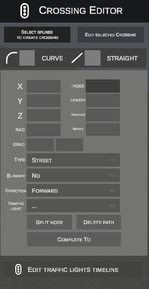
1. Creating Crossings from Splines (SELECT SPLINES TO CREATE CROSSING)
Transforms any layout of interconnected road splines into a dedicated OMSI intersection object.
Step-by-Step Creation Workflow:
- Click SELECT SPLINES TO CREATE CROSSING in the upper toolbar:

- The button label changes to CREATE CROSSING FROM SELECTION:

- Select all splines comprising the intersection:
- Click LMB on an individual spline to select it (highlights green).
- Drag LMB to draw a selection rectangle (box select) over multiple segments.
- Hold Shift to add splines to the selection.
- Hold Ctrl to remove splines from the selection.
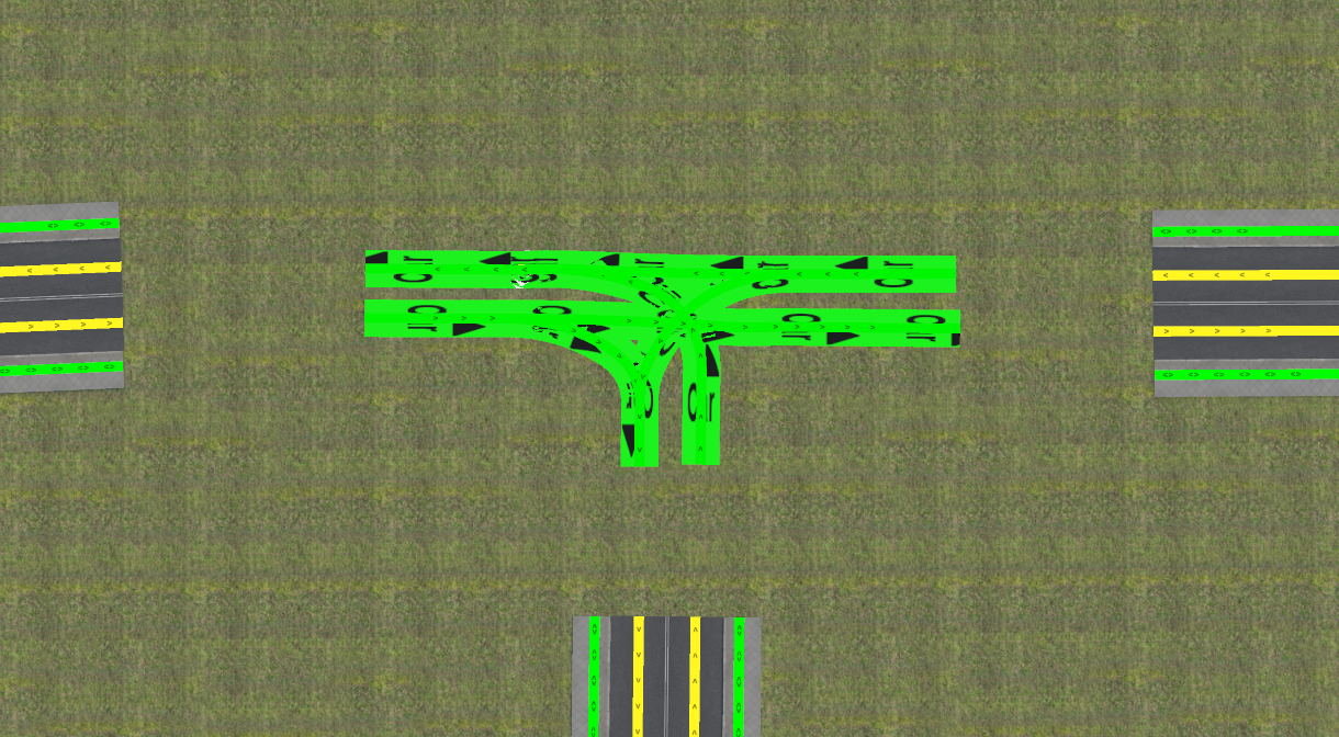
- Click CREATE CROSSING FROM SELECTION.
- The editor automatically:
- Removes the selected spline segments from the scene.
- Converts spline traffic paths (
[path]) into local object paths. - Creates the folder structure in
SceneryObjects/nEditorGenerated/<map_name>/<object_ID>/along with geometry (model.x), textures, and.scodefinition files. - Inserts the newly generated crossing object onto the scene with a red AI Cube origin handle:
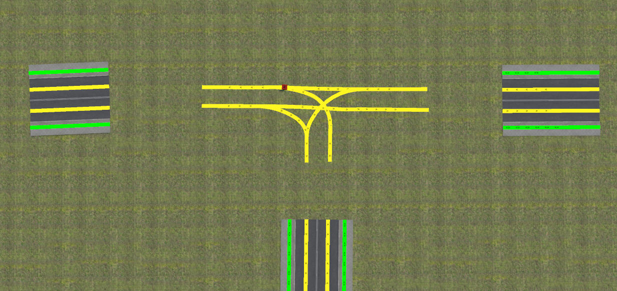
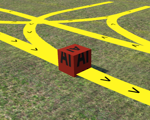
2. Crossing Edit Mode and Workspace Boundary (EDIT SELECTED CROSSING)
To enter detailed path geometry editing:
- Click LMB to select the crossing object (or its AI Cube) in the scene (highlights yellow).
- Click EDIT SELECTED CROSSING in the side panel:
- A yellow circle delimiting the Workspace Boundary appears around the intersection:
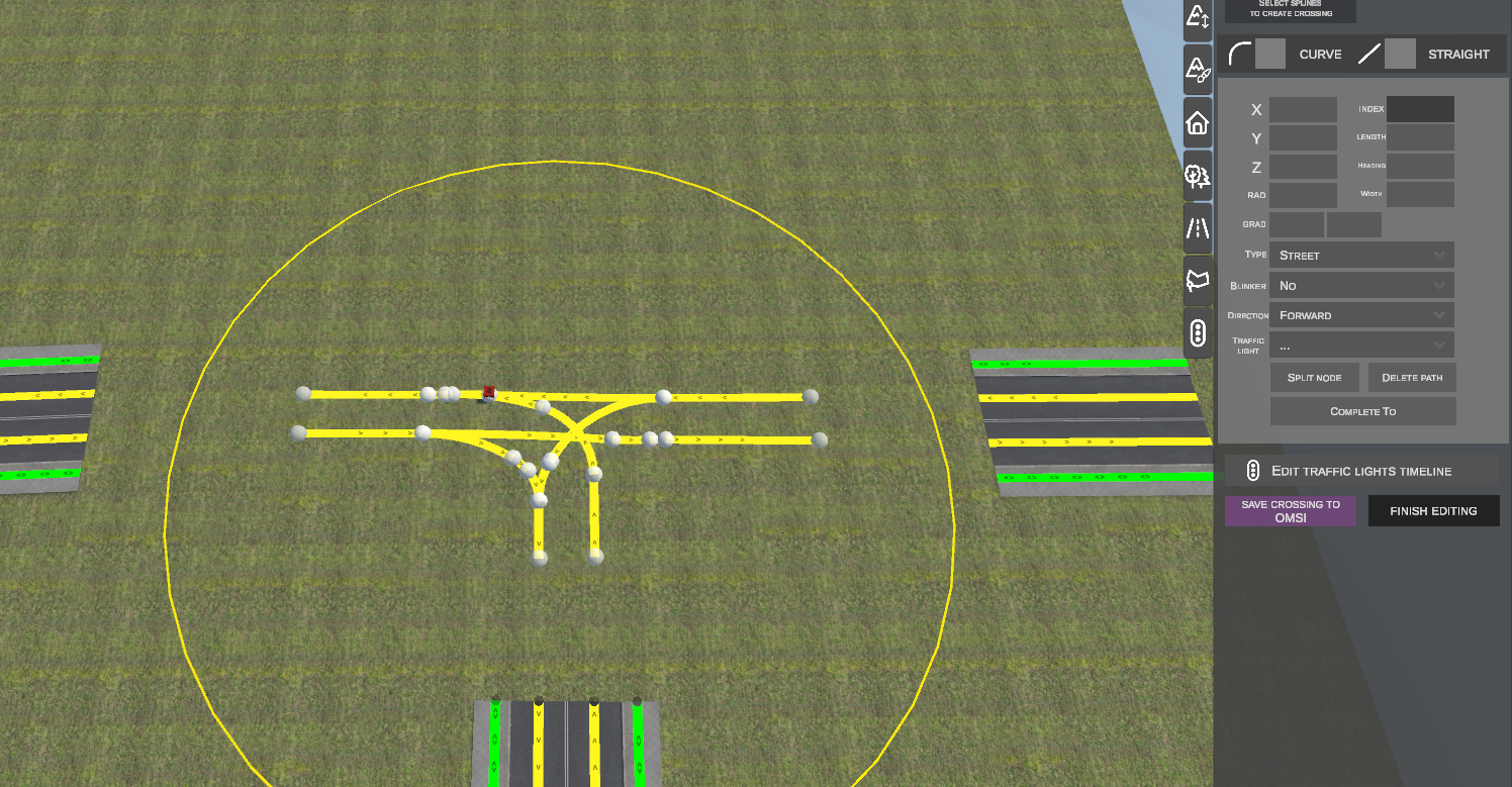
Dynamic Nodes vs Static Nodes:
The editor displays two types of control nodes within the workspace:
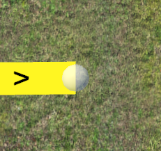
- Dynamic Nodes: Translucent spheres positioned at endpoints of internal crossing paths. These support full translation, elevation adjustment, tangential rotation, and subdivision.
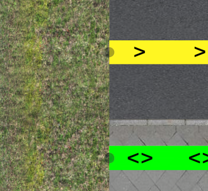
- Static Snap Nodes: Dark nodes located at the perimeter on endpoints of external splines entering the intersection. Moving dynamic nodes snap automatically to these static points, ensuring seamless road connectivity. They can also be selected (highlighting blue on hover and red when selected) to be used as a start or destination in the COMPLETE TO tool, though they cannot be freely translated.
3. Manipulating Nodes and Creating Traffic Paths
A. Moving Nodes Horizontally (Key G)
- Click LMB on a dynamic node (highlights red).
- Press G.
- Move the cursor. The node translates along the horizontal plane while connected path segments adapt dynamically.
- Moving near another dynamic or static node activates automatic snapping.
- Click LMB or press Enter to confirm. Press Esc to cancel.
B. Tangent Locking and Alignment (Key Alt)
- Axis Lock While Moving: Pressing Alt while moving a node (G) locks translation along its existing tangent heading, preventing angle kinks at joints.
- Align to Predecessor: With a resting node selected, pressing Alt automatically recomputes the path heading to match tangentially with the preceding segment.
C. Vertical Height Adjustment (Key Z)
- Select a dynamic node and press Z.
- Move the mouse vertically to adjust elevation.
- Holding Ctrl enables discrete 0.1 m step snapping.
- Click LMB or press Enter to confirm.
D. Creating New Paths (Key N)
- Select an endpoint of an existing path and press N:
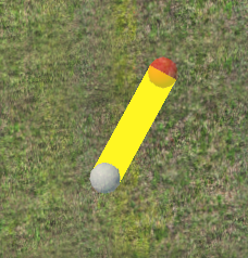 (With no node selected, pressing N and clicking LMB on the ground starts a new path from scratch).
 - While extending the segment, press R (or toggle in the panel) to switch geometry types:
- STRAIGHT – linear segment.
- CURVE – arc with radius computed live from mouse position:
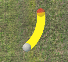
- Click LMB to anchor the new path endpoint.
E. Automated Path Joining (COMPLETE TO)
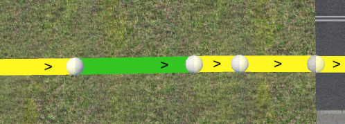
COMPLETE TO connects two selected nodes (both internal crossing dynamic nodes and external spline static snap nodes) with a mathematically fitted tangent curve and smooth vertical Hermite profile:
- Select the start node with LMB.
- Hold Shift and click LMB on the target node:
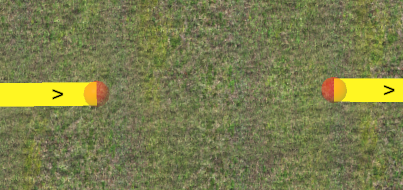
- Click COMPLETE TO in the side panel.
- The editor bridges the gap with a fitted transition arc:
F. Splitting Nodes (SPLIT NODE) and Deleting Paths (DELETE PATH)
- SPLIT NODE: When multiple paths converge at a single vertex, clicking SPLIT NODE separates joined nodes by 0.5 m along their axes, allowing independent editing of branches.
- DELETE PATH / Del key: Deletes the selected path and its associated nodes from the crossing.
4. AI Traffic Path Properties (Property Inspector)
Selecting a path or node displays its properties in the side panel:
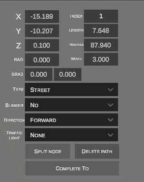
| Parameter | Unit | Description |
|---|---|---|
| X / Y / Z | Meters | Coordinates of path origin in local object space. |
| INDEX | Integer | Internal path index within the crossing object. |
| LENGTH | Meters | Longitudinal path length. |
| HEADING | Degrees (0.0° - 360.0°) |
Initial azimuth heading angle. |
| RAD | Meters | Curve radius (0.000 = straight). |
| WIDTH | Meters | Traffic corridor width (default 3.000 m for lanes). |
| GRAD | Percentage | Longitudinal vertical slope. |
| TYPE | Dropdown | Allowed traffic type: Street (vehicles), Sidewalk (pedestrians), Railroad (trams/trains). |
| DIRECTION | Dropdown | Directionality: Forward, Reverse, Both (two-way). |
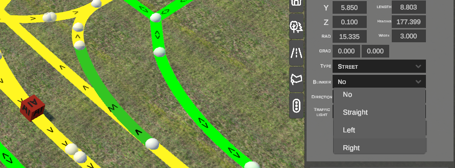
| BLINKER | Dropdown | AI turn signal indicator: No, Straight, Left, Right. |
| TRAFFIC LIGHT | Dropdown | Traffic signal group controlling this path (e.g., None, Road_1, Road_2, Road_1_PED). |
Blinker Configuration (BLINKER):
Setting BLINKER forces AI vehicles to activate the corresponding turn indicator upon entering the lane:
5. Traffic Lights Timeline
nEditor features an integrated traffic signal cycle timeline editor with live 3D animation preview.
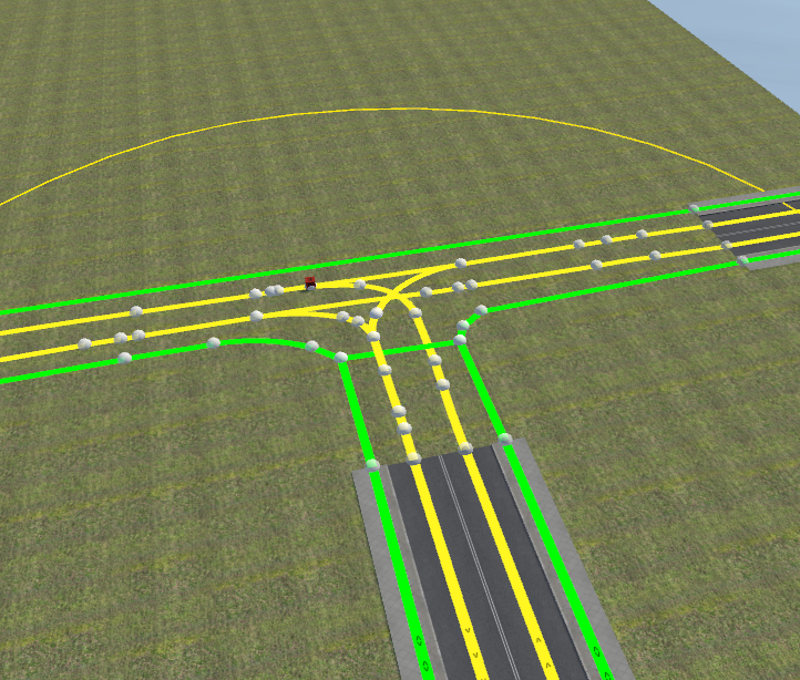
Crossing view before signal setup:
A. Timeline Editor Dialog (CROSSING EDITOR TIMELINE)
Clicking EDIT TRAFFIC LIGHTS TIMELINE opens the signal group and phase configuration dialog:

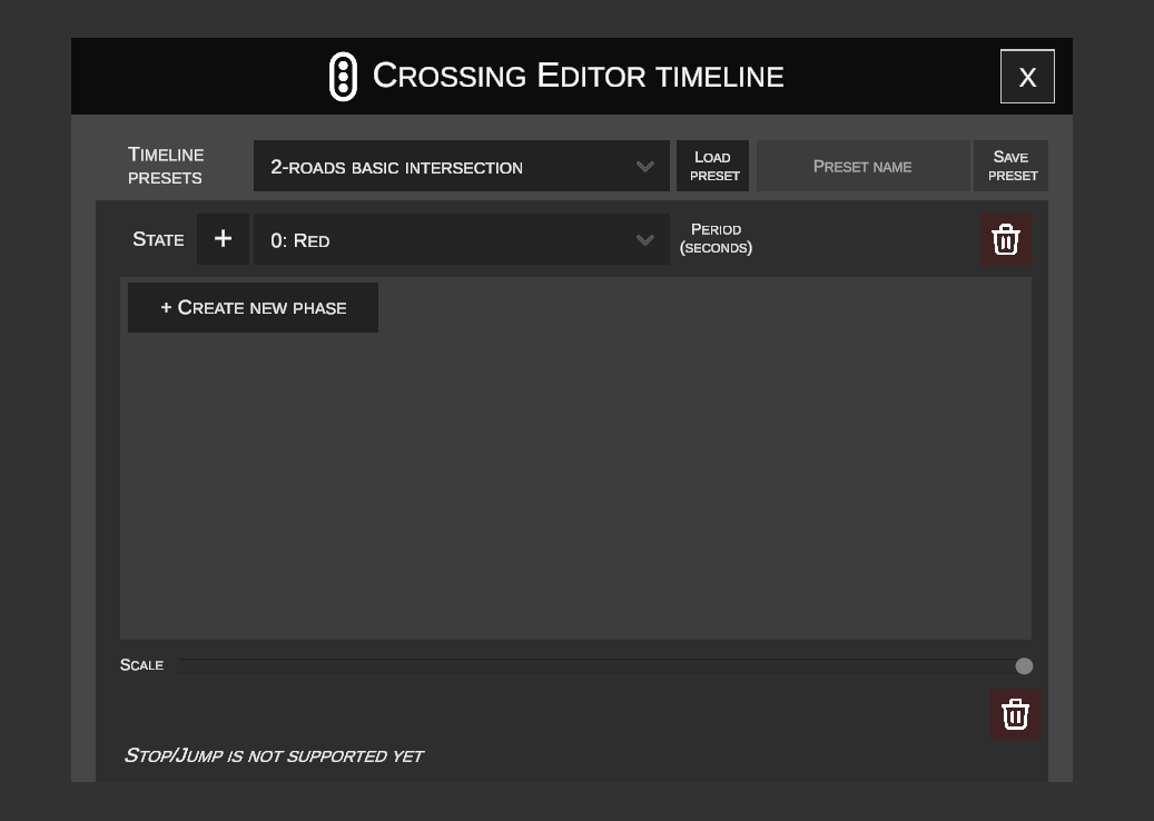
Define signal groups (e.g., Road_1, Road_2, Road_1_PED) and timing phases:
- STATE: Signal light state matching the OMSI engine standard:
0..2: Red– red stop light.3..5: Yellow (Red -> Green)– red-amber (prepare to proceed).6..8: Green– green proceed light.9..11: Yellow (Green -> Red)– amber clearance warning.12: Off– signal disabled / flashing amber.- PERIOD (SECONDS): Phase duration in seconds.
- + CREATE NEW PHASE: Appends another phase block to the selected group.
- Red Trash Icon: Deletes a phase or signal group.
- SCALE: Horizontal zoom slider for the timeline track.
B. Timeline Presets
Instead of manual interval timing, load pre-configured templates or save custom programs:
- Under TIMELINE PRESETS, open the template dropdown (e.g.,
2-roads basic intersection,3-roads basic intersection,4-roads basic intersection):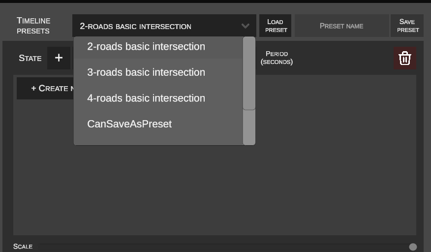
- Click LOAD PRESET.
- Synchronized signal groups populate the timeline with color-coded intervals:
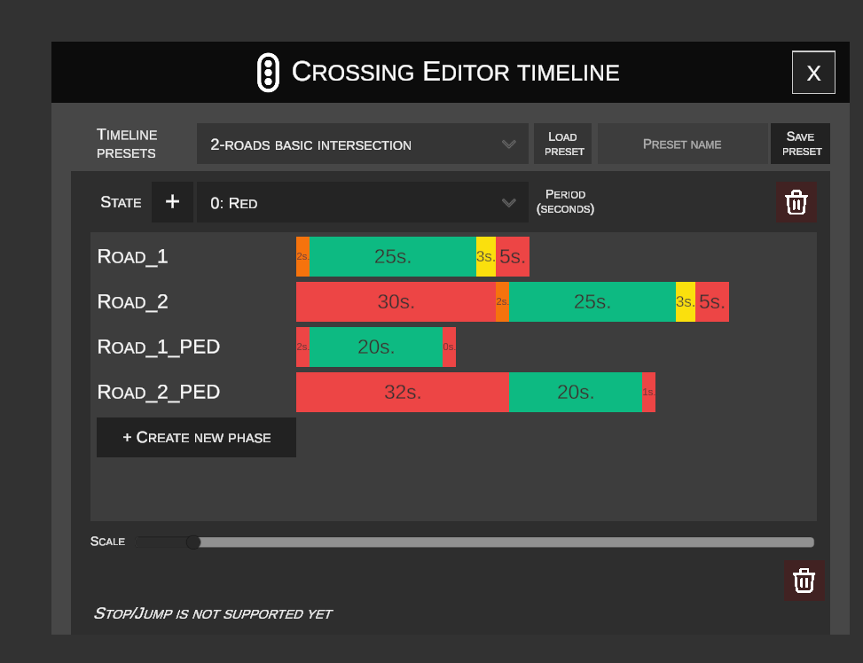
- To save a setup, enter a name in PRESET NAME and click SAVE PRESET.
C. Live Cycle Preview (Timeline Bottom Bar)
A floating preview toolbar docks across the bottom of the viewport:

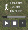
- Play (
▶): Starts looped cycle playback. - Stop (
■): Halts animation and resets timer to0.0s. - Timer Display: Shows active cycle elapsed time in seconds.
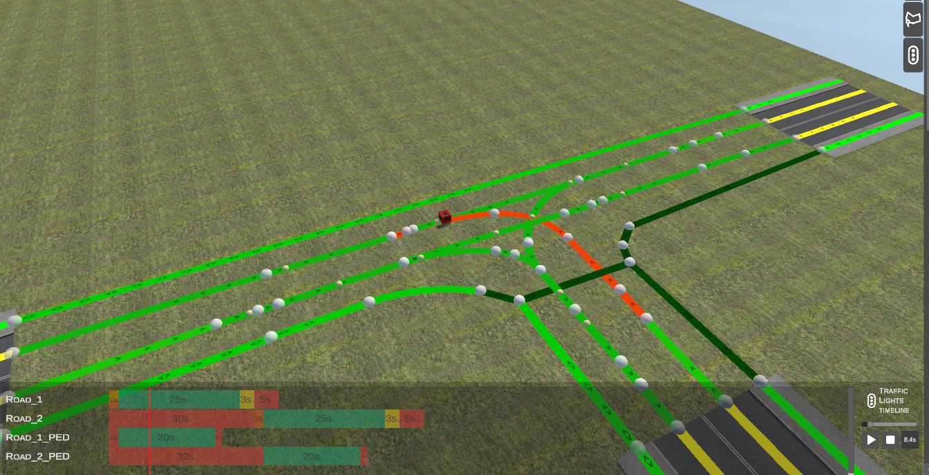
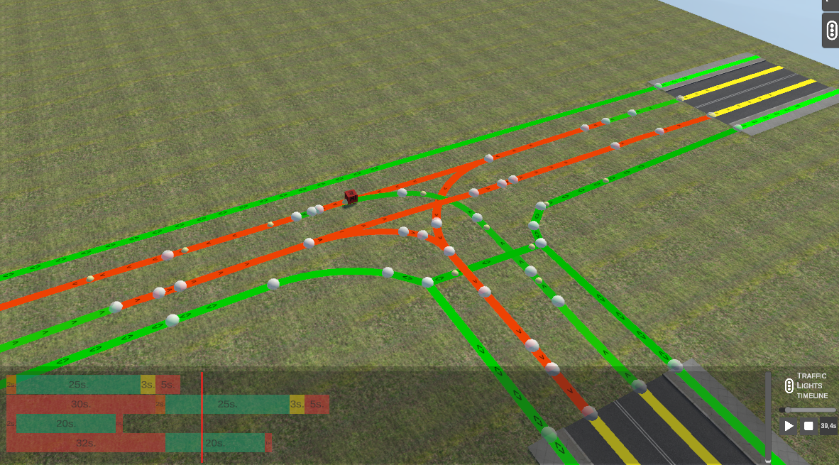
- Interactive 3D Preview: As the red playhead advances across timeline tracks, corresponding traffic paths dynamically illuminate in the 3D scene:
- Green light paths highlight in green.
- Red light paths highlight in red / orange.
D. Assigning Signal Groups to Paths
To enforce signal stops for AI traffic:
- Select a traffic path in the intersection.
- In the TRAFFIC LIGHT dropdown, assign the corresponding group (e.g.,
Road_1orRoad_2):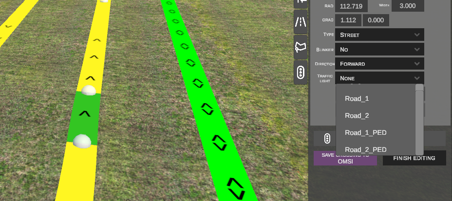
6. Linking Physical Traffic Signal Objects in the Objects Tab
Once intersection signal logic is configured, link physical signal scenery objects:
- Navigate to the Scenery Objects tab and place a traffic signal model near the curb:
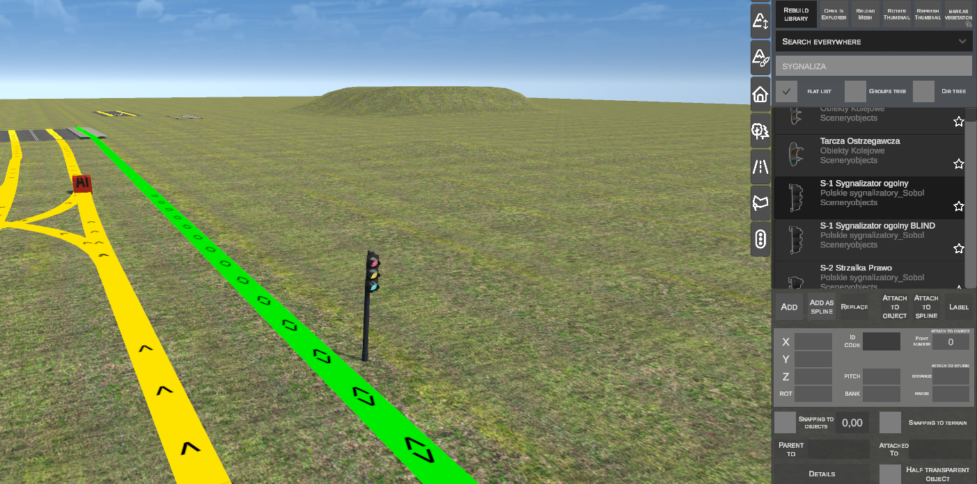
- In the object property panel, click PARENT TO:
- Click the intersection's
AI Cubein the scene (or enter its ID number, e.g.,190). - Below
DETAILS, a TRAFFIC LIGHT dropdown appears with all groups defined on that crossing (Road 1,Road 2,Road 1 PED, etc.):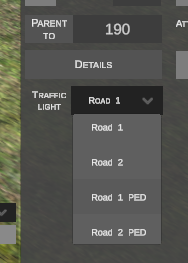
- Select the appropriate group. The physical signal is now synchronized with intersection cycles.
7. Saving Crossing Changes (SAVE CROSSING TO OMSI)
Upon completing geometry and signal configuration:

- SAVE CROSSING TO OMSI: Commits modified paths, elevations, blinkers, and signal programs to the
.scofile on disk and the editor database. - FINISH EDITING: Exits intersection edit mode, hides node handles, and returns to standard viewport mode.
8. Keyboard Shortcuts Reference
| Shortcut | Context | Function |
|---|---|---|
| N | Selected crossing node | Extrudes new path from selected node. |
| N | No node selected | Starts new path from clicked point on ground. |
| R | During path creation | Toggles path geometry between straight (STRAIGHT) and arc (CURVE). |
| G | Selected dynamic node | Translates node horizontally with automated snapping. |
| Alt | During move (G) | Constrains translation along tangent heading. |
| Alt | Selected node (resting) | Aligns azimuth tangentially to predecessor path. |
| Z | Selected dynamic node | Adjusts node elevation vertically via mouse dragging. |
| Ctrl | During height adjustment (Z) | Snaps elevation in 0.1 m intervals. |
| Shift + LMB | Two selected nodes | Selects start and end nodes for COMPLETE TO arc bridging. |
| Shift + LMB / Box | Spline selection mode | Adds splines to selection prior to crossing generation. |
| Ctrl + LMB / Box | Spline selection mode | Removes splines from selection. |
| Del | Selected path | Deletes selected path from crossing. |
| LMB / Enter | During transform | Confirms translation or placement. |
| RMB / Esc | During transform | Cancels operation and restores previous geometry. |