Terrain Topology Tab
The Terrain Topology tab (indicated by the mountain icon with elevation arrows in the side toolbar) is a powerful toolset for sculpting and reshaping your map's elevation model.
It enables smooth organic terrain sculpting with 3D brushes, precise vertex editing on the elevation grid, automated embankment and cutting generation along roads and railways, water surface configuration, and direct import of real-world Digital Elevation Models (DEM / LiDAR / SRTM).
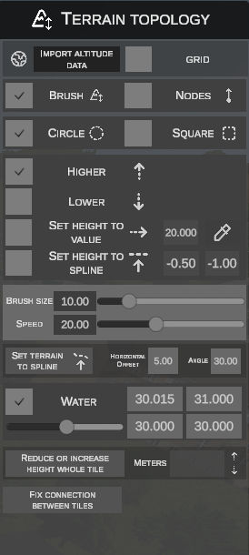
1. Top Bar: Altitude Data Import and Helper Grid
Two global tools are located at the top of the panel:
- IMPORT ALTITUDE DATA (globe icon button) – opens the satellite and geodetic altitude import window.
- GRID (checkbox) – toggles display of the topographic helper grid directly on the terrain surface.
2. Importing Elevation from External Sources (Import altitude data)
The import dialog populates the tile's height grid with data from professional cartographic and satellite sources:
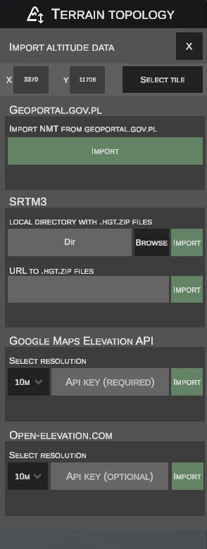
Selecting the Target Tile
- The X and Y fields display the coordinates of the currently active terrain tile.
- Clicking SELECT TILE allows you to interactively click any tile in the 3D viewport to set it as the import target.
Available Data Providers:
- Coverage: Poland (highest geodetic accuracy, down to 1 meter).
- Mechanism: Uses tile GPS coordinates to pull Digital Elevation Model data directly from official Geoportal repositories in ARC/INFO ASCII Grid (
.asc) format. - Usage: Click IMPORT under the Geoportal section – the editor transforms coordinates and applies heights automatically.
- Coverage: Worldwide elevation data collected by Space Shuttle Endeavour.
- Local Archive Mode: Use BROWSE to point to a folder containing
.hgt.ziparchives on your drive, then click IMPORT. - Web Archive Mode (URL): Enter the direct download URL in the URL TO .HGT.ZIP FILES field and click IMPORT: Example sources: 1 2
- Coverage: Global elevation dataset powered by Google infrastructure.
- Requirements: Requires your own API key entered in the API KEY (REQUIRED) field.
- Settings: The SELECT RESOLUTION dropdown defines sampling density (e.g., every
10M). Smaller values provide higher fidelity but require more API calls.
- Coverage: Free and open alternative to commercial elevation services.
- Requirements: API key is optional (API KEY (OPTIONAL)).
- Settings: Select sampling density (e.g.,
10M) and click IMPORT. Smaller values yield greater precision at the cost of more queries.
3. Editing Modes: Brush vs Nodes
A toggle switch right below the import bar controls how you manipulate the terrain:
- BRUSH – organic sculpting using a 3D spherical or box brush with adjustable radius and strength.
- NODES – surgical micro-editing of specific vertex coordinates on the elevation mesh.
4. Working in Brush Mode
In brush mode, the mouse cursor over the terrain turns into a 3D wireframe bounding shape:
A. Brush Shape
- CIRCLE – circular brush with a radial smooth falloff (SmoothStep).
- SQUARE – square brush, useful for regular embankments, structural excavations, and road shoulders.
B. Brush Actions
- HIGHER (up arrow) – smoothly raises the terrain under the brush while holding LMB.
- LOWER (down arrow) – lowers the terrain under the brush.
- SET HEIGHT TO VALUE – levels the terrain to a specified target altitude:
- Enter the target height in the adjacent field (e.g.,
20.000m). - The eyedropper button samples the height from any clicked point on the terrain.
- Enter the target height in the adjacent field (e.g.,
- SET HEIGHT TO SPLINE – snaps and pulls terrain to the altitude of a nearby road or track spline, preventing unintended road clipping:
- Center brush offset (first input, e.g.,
-0.50) – height offset applied at the core of the brush (e.g., a negative value creates a trench beneath roadbeds or track ballast). - Spline relative height offset (second input, e.g.,
-1.00) – maximum height ceiling relative to the spline surface (e.g.,-1.00ensures terrain never rises higher than 1 meter below the road grade).
- Center brush offset (first input, e.g.,
C. Brush Parameters
- BRUSH SIZE (slider and text field) – diameter / influence radius of the brush in meters (e.g.,
10.00). - SPEED (slider and text field) – deformation rate and intensity when dragging the mouse.
Automatic Scenery Adaptation
While sculpting terrain with brushes, scenery objects within the affected area automatically adjust their vertical position to stay on the newly sculpted surface, preventing floating or buried models.
Exception: Objects with the
[absheight](absolute height) parameter maintain their fixed world altitude and are not moved by terrain changes.
5. Forming Embankments and Cuttings (Set terrain to spline)
Eliminates tedious manual shaping of verges along extended road and railway alignments:
| Parameter | Description |
|---|---|
HORIZONTAL OFFSET (e.g., 5.00) |
Width of the flat shoulder verge in meters measured from the spline edge. |
ANGLE (e.g., 30.00) |
Slope angle in degrees at which the cutting or embankment slopes toward natural ground level. |
Embankment Creation Procedure:
- Set the desired horizontal offset and slope angle.
- Click SET TERRAIN TO SPLINE to enter target selection mode:
- Hovering over a spline highlights it in yellow.
- Clicking LMB selects the spline (highlighted in cyan). You can select multiple splines.
- Holding Ctrl and clicking removes a spline from the selection.
- Click SET TERRAIN TO SPLINE again – the editor generates a seamless embankment along all selected segments and updates the terrain tiles.
- Press Esc or RMB to cancel selection mode without applying changes.
6. Working in Nodes Mode
Switching to NODES enables direct control over individual grid vertices (60×60 point resolution per tile):
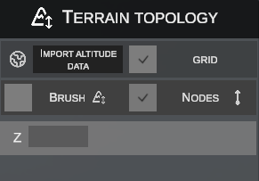
Selecting Vertices:
- LMB Click on a vertex selects a single point.
- Click and Drag LMB opens a rectangular bounding box (box selection) to select groups of vertices.
- Holding Ctrl toggles points in or out of the active selection.
Adjusting Elevation:
- Key Z (Interactive Move):
- Select the desired vertices.
- Press Z on your keyboard.
- Move the mouse vertically (up / down) to adjust height in real time.
- Click LMB or press Esc to confirm the new elevation.
ZNumeric Field:- Entering a specific value into the
Zfield in the side panel sets that exact elevation across all selected vertices.
- Entering a specific value into the
7. Water Bodies and Surfaces (Water)
Dedicated section for defining water surfaces on a tile:
- WATER Checkbox – enables or disables the water sheet on the active tile.
- Water Level Slider – adjusts water altitude across the entire tile uniformly.
- Four Corner Fields (
0.000/0.000/0.000/0.000):- OMSI 2 defines water sheets via four corner heights per tile.
- This allows creating both flat lakes/ponds and graded, sloping rivers and streams with natural downward currents.
8. Global Tile Utilities (Bottom Panel)
Two bulk operation tools are provided at the base of the panel:
Whole Tile Height Adjustment (Reduce or increase height whole tile)
Allows you to precisely raise or lower the entire elevation grid of a selected terrain sector with a real-time live preview in the 3D scene:
- Click the REDUCE OR INCREASE HEIGHT WHOLE TILE button at the bottom of the panel.
- The button label will change to Confirm height change.
- The editor will enter tile selection mode – hovering over a tile highlights its boundary with a yellow outline.
- Click Left Mouse Button (LMB) on the tile you wish to adjust.
- The selected sector will be highlighted with a green outline.
- The METERS input field (defaults to 1.00) and the height step buttons become active:
- Up Arrow Button (▲) – raises the entire tile by the specified number of meters.
- Down Arrow Button (▼) – lowers the entire tile by the specified number of meters.
- Each click immediately recalculates and updates the real-time terrain preview in the 3D viewport. Height adjustments can be accumulated by clicking multiple times.
- Confirm or cancel the operation:
- Confirm: Click Confirm height change – the new height is saved to the map sector database and the tile reloads.
- Cancel: Press the Esc key (or exit the mode without making changes) – the operation is cancelled and the tile instantly reverts to its original elevation.
Stitching Inter-tile Edges (Fix connection between tiles)
Repair tool that seals geometric seams and cracks between adjacent terrain tiles:
- Click FIX CONNECTION BETWEEN TILES.
- Hover over the boundary between two tiles – the edge highlights with a guide indicator.
- Click Left Mouse Button – the editor averages and matches vertex elevations seamlessly along the entire boundary seam.