Splines Tab
The Splines tab (accessible via the road icon in the side toolbar) is used for designing and editing road networks, tram/rail tracks, sidewalks, bicycle paths, horizontal road markings, and guardrails.
The editor offers two distinct editing paradigms: geometric vertex manipulation (NODES) and direct whole-segment manipulation (FRAGMENTS), complemented by advanced auto-joining, vertical alignment, and geometry cloning tools.
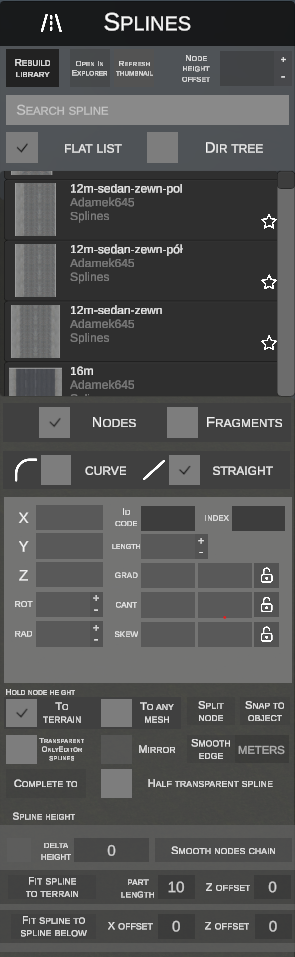
1. Toolbar and Global Parameters
The top toolbar provides profile library management and a global node display offset:
- REBUILD LIBRARY – rescans simulator folders and updates the list of available
.slifiles. - OPEN IN EXPLORER – opens the folder containing the selected spline profile in Windows Explorer.
- REFRESH THUMBNAIL – regenerates a preview thumbnail for the selected profile.
- NODE HEIGHT OFFSET (with
+/-buttons): Globally shifts the vertical rendering height of spherical manipulation handles (markers) relative to spline surfaces.- Allows lowering or raising node handles so they align flush with the road surface (e.g., adjusting from
0.000to-0.090):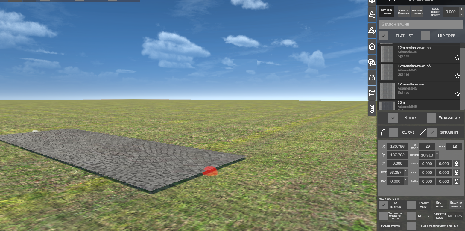
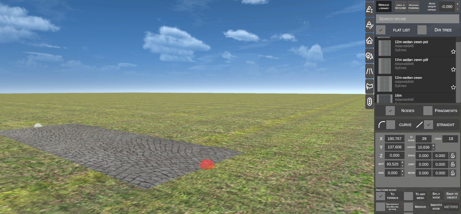
- Allows lowering or raising node handles so they align flush with the road surface (e.g., adjusting from
2. Library Browsing and Profile Selection
Spline profiles can be browsed in two modes:
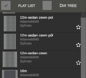
Displays a list of profiles with cross-sectional texture previews, profile names, folders, and favorite stars.
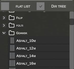
Mirrors the physical folder hierarchy within the Splines directory on disk.
- SEARCH SPLINE input: Filters the list by name or path.
- Favorites Bar: Clicking the star pins the profile to the bottom quick access bar.
3. Selecting Edit Mode: NODES vs FRAGMENTS
A toggle switch in the panel determines the interaction workflow:
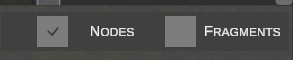
| Mode | Scope |
|---|---|
| NODES | Operates on vertices (geometric control endpoints). Used for routing road alignments, drawing curves, tuning curve radii, smoothing kinks, and adjusting vertex elevations. |
| FRAGMENTS | Operates on entire spline segments as discrete objects. Used for moving, rotating, subdividing (Cut), mirroring (Mirror), and profile swapping (Replace). |
4. Nodes Mode (NODES) – Creation and Modification
In NODES mode, spherical control points (nodes) are rendered at spline endpoints. The active/selected node highlights in red, while unselected nodes appear white.
A. Creating a New Spline from Scratch (Step by Step)
- Select a spline profile from the library (or bottom favorites bar).
- Ensure no node is selected (press Esc).
- Press the N key. The first point marker will attach to your mouse cursor.
- Click LMB on the ground to anchor the starting node.
- Move the cursor – the editor stretches a real-time spline preview.
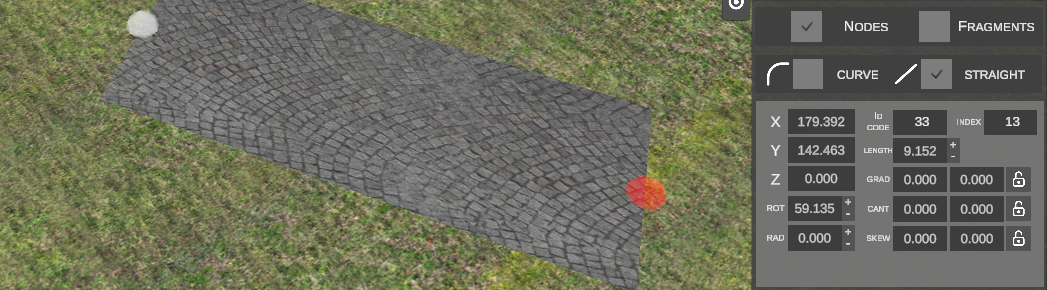
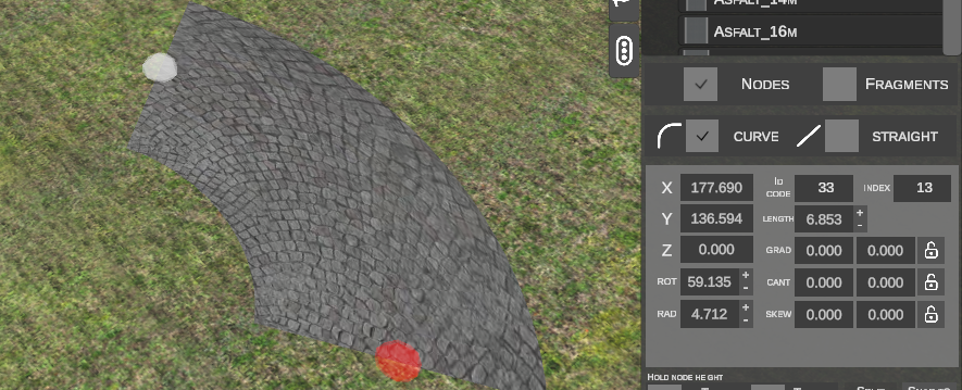
- While dragging, press R to toggle between geometry modes:
- STRAIGHT (linear segment):
- CURVE (arc with radius computed dynamically from cursor position):
- STRAIGHT (linear segment):
- Click LMB to anchor the end node.
- The editor automatically chains to extrude the next segment from the newly placed node. Press Esc to finish.
B. Extruding a Spline from an Existing Node
- Click LMB on an end node of an existing spline (highlights red).
- Press the N key.
- The editor immediately begins extending a new segment preserving geometric continuity and tangential heading:
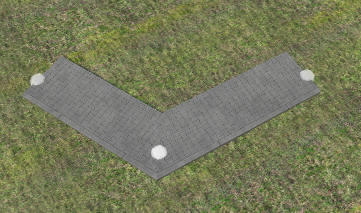
- Position the endpoint and click LMB.
C. Snapping to Another Node (Ctrl Snapping)
While moving a node or extending a new segment:
- Hold the Ctrl key.
- Bring the cursor near any other node on the scene:
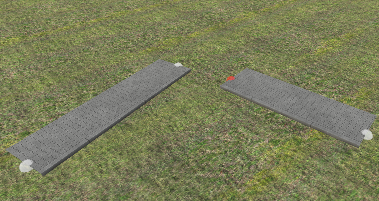
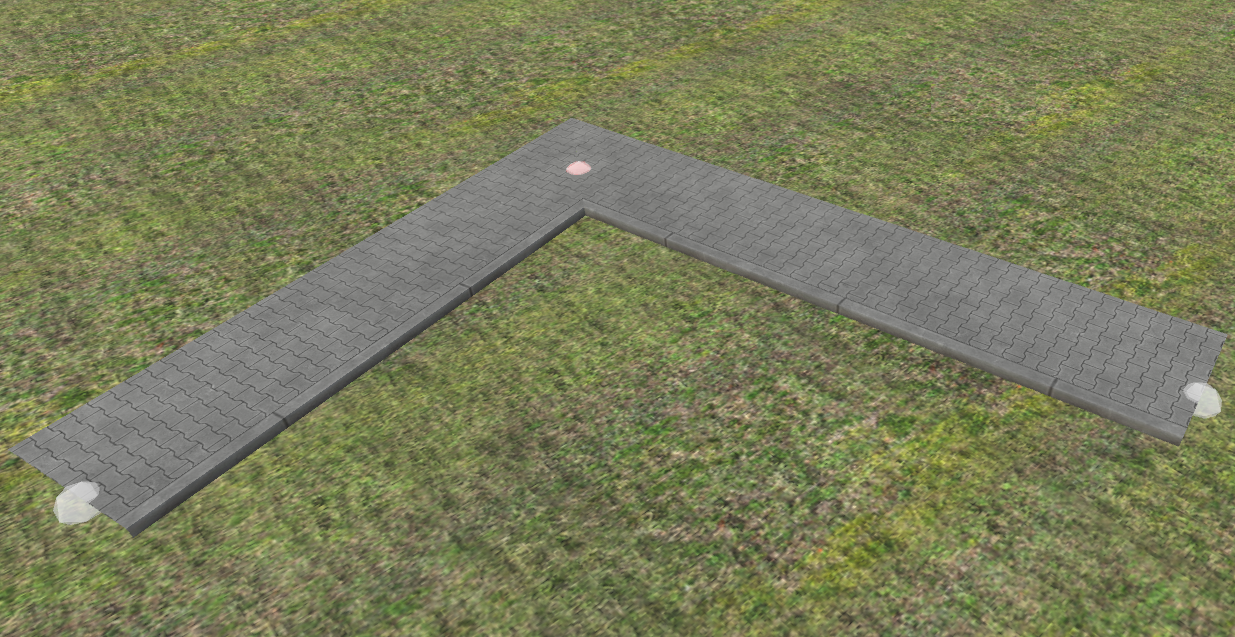
- The node will snap and merge permanently with the target node:
5. Spline Geometry Parameters (Property Inspector)
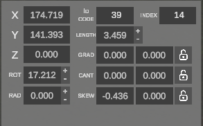
Selecting a node reveals the geometric properties of the active segment in the side panel:
| Field | Unit | Description |
|---|---|---|
| X / Y / Z | m | Coordinates of the start node in tile space. |
| ID CODE | – | Unique internal numeric identifier in the OMSI map file. |
| INDEX | – | Spline index on the tile. |
| LENGTH | m | Segment length (+ / - buttons adjust by step size). |
| ROT | ° | Initial heading angle around vertical axis. + / - buttons rotate the segment. |
| RAD | m | Horizontal curve radius. A value of 0 denotes a straight segment (STRAIGHT). Non-zero defines turning radius (CURVE). |
| GRAD | % | Longitudinal grade (gradient slope) at start and end. Lock icon couples equal values. |
| CANT | m / ° | Superelevation (cross slope banking) at start and end. |
| SKEW | – | Skew angle across start and end profile joints. |
6. Controlling Elevation and Node Snapping
A. Height Snapping Modes (HOLD NODE HEIGHT)
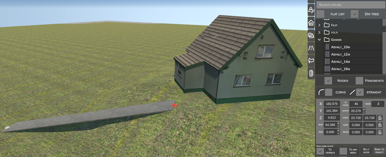
- TO TERRAIN: The node continuously matches its Z height to the terrain surface beneath it:
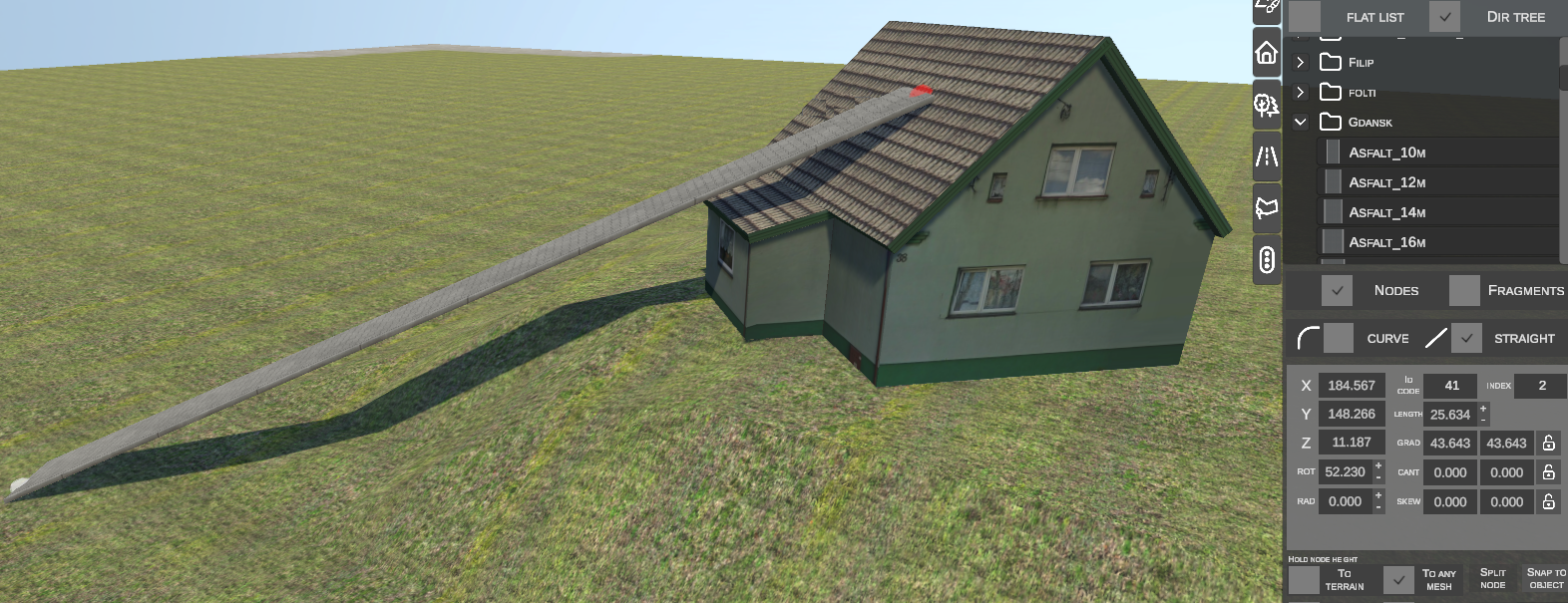
- TO ANY MESH: The node catches the altitude of any 3D collision mesh under the cursor (enables laying splines directly over bridge decks, building roofs, or elevated ramps):
B. Elevation Adjustments: GRADIENT vs DELTA HEIGHT
The lower panel hosts the DELTA HEIGHT toggle:
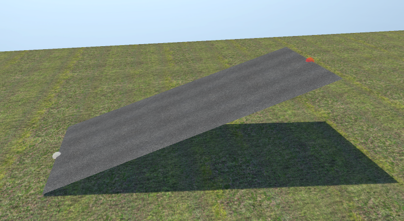
- Standard / Linear (key Z):
Maintains a linear slope. Sharp gradient kinks form at the node apex:
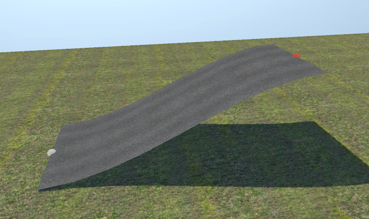
- S-curve (Dual Smooth) (key X):
The endpoint altitude is defined by an elevation difference (Delta Height). The editor forms a smooth parabolic vertical curve with flat tangents at both ends (StartGrad = 0, EndGrad = 0), eliminating abrupt crests and sags:
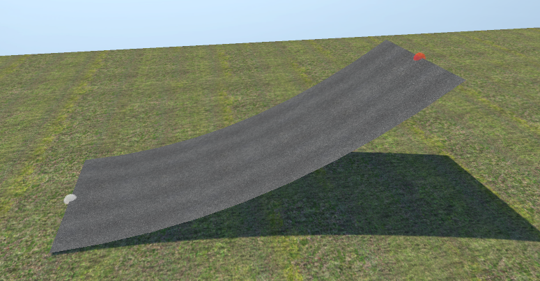
- Sag Curve (Ease-in) (key C):
Transition curve with horizontal tangent at the base / stationary node and steep tangent at the moving node:
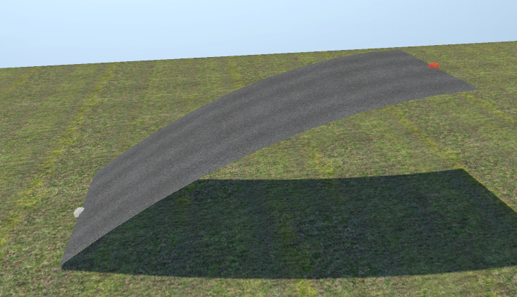
- Crest Curve (Ease-out) (key V):
Transition curve with steep start at the base and horizontal tangent at the crest / moving node:
7. Advanced Node Editing Utilities
A. Splitting a Node (SPLIT NODE)
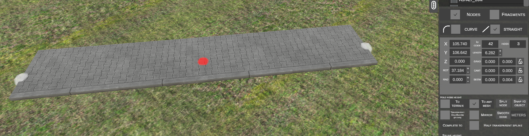
Separates a shared node connecting two or more splines into independent points:
- Select the shared node:
- Click SPLIT NODE.
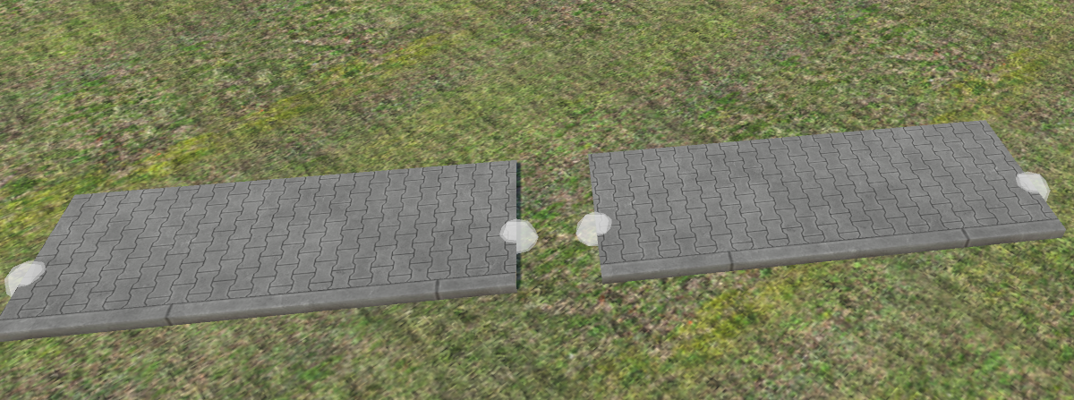
- The shared joint splits into independent nodes for each spline, allowing them to be moved apart:
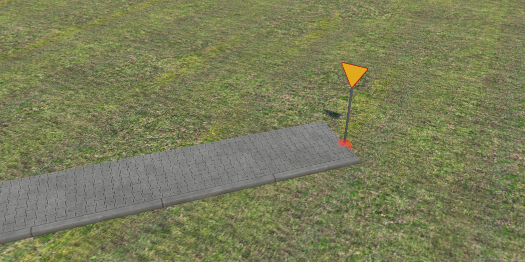
B. Snapping to Scenery Objects (SNAP TO OBJECT)
Binds node coordinates to a 3D scenery object:
- Select the spline node:
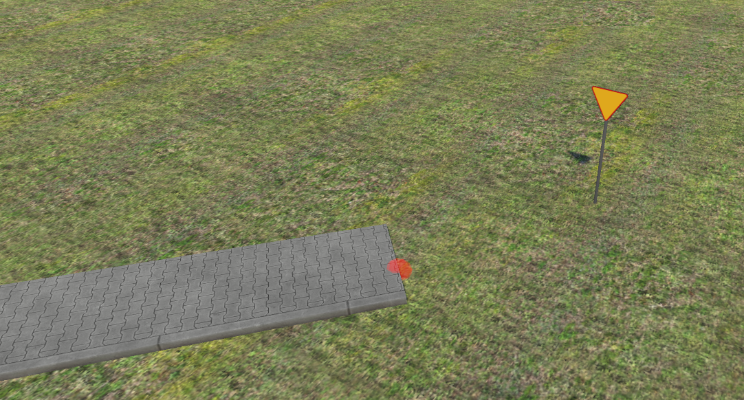
- Click SNAP TO OBJECT.
- Hover over the target scenery object (e.g., base of a signpost) and click LMB:
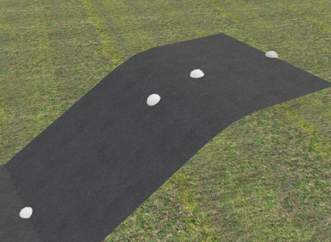
C. Filleting and Smoothing Kinks (SMOOTH EDGE)
Inserts a transition fillet curve at a sharp angle between two splines:
- Select the corner vertex:
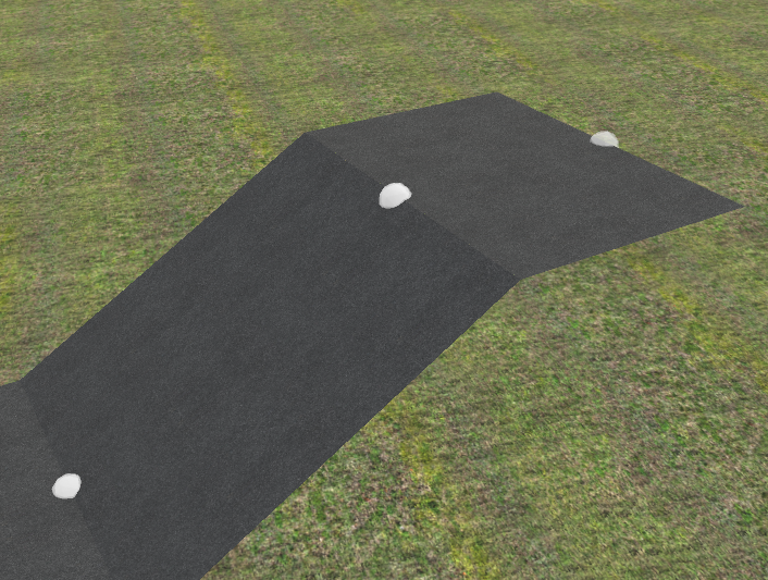
- Enter the fillet radius in meters in the adjacent field (e.g.,
2m). - Click SMOOTH EDGE.
- The corner is replaced with a smooth tangent arc:
D. Automated Path Closing (COMPLETE TO)
Connects two separated nodes with a mathematically fitted tangent curve:
- Select the first node with LMB.
- Hold Shift and select the second node on another spline:
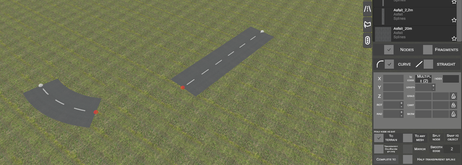
- Click COMPLETE TO.
- The editor computes tangents and radius, inserting the connecting curve automatically:
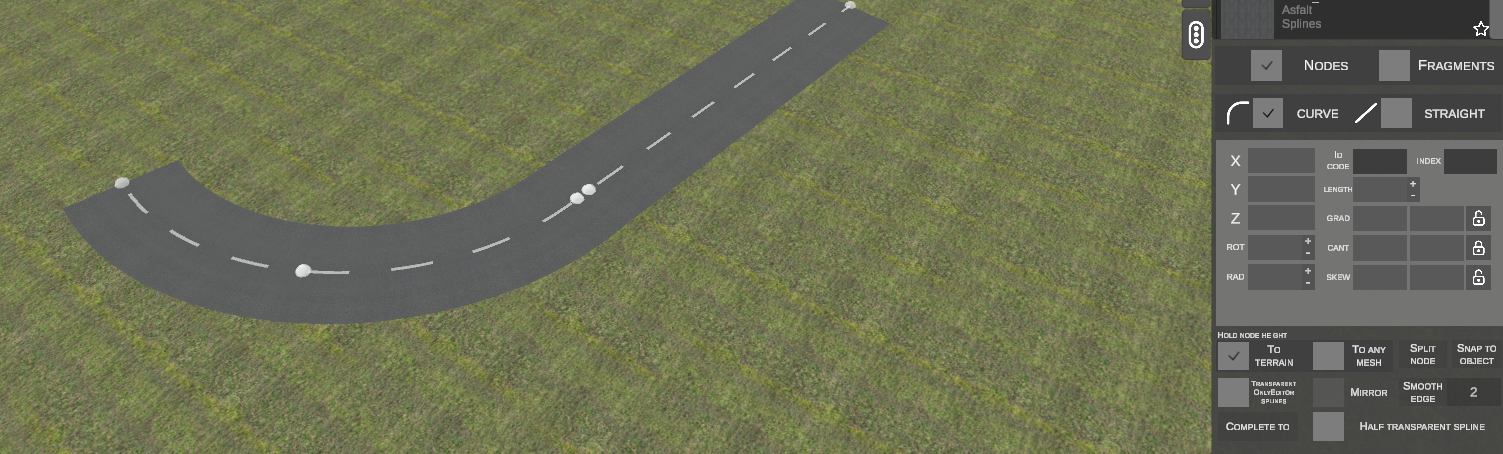
Selection Order
nEditor connects the first selected node to the second node (opposite to the original OMSI editor).
E. Longitudinal Grade Smoothing (SMOOTH NODES CHAIN)
Smooths uneven grade steps across a series of nodes:
- Select a chain of nodes along an uneven slope:
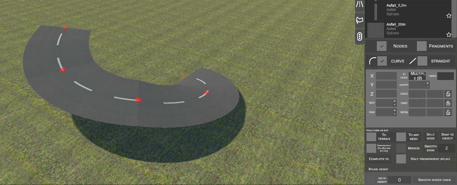
- Click SMOOTH NODES CHAIN.
- Elevations across all intermediate vertices are recalculated along an idealized uniform grade:
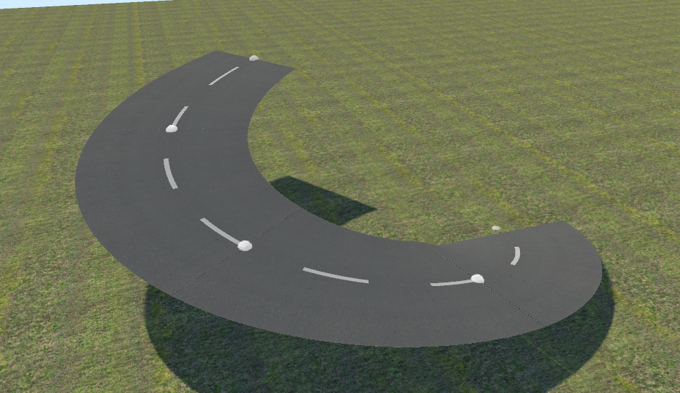
F. Draping to Ground (FIT SPLINE TO TERRAIN)
Subdivides an extended spline into smaller segments conforming to terrain undulations:
- Select the endpoints of a spline crossing a hill:
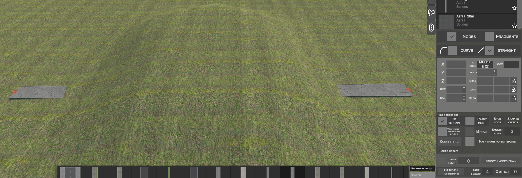
- Configure parameters:
- PART LENGTH (e.g.,
4or10m): Maximum segment subdivision step. - Z OFFSET (e.g.,
0m): Vertical clearance above the ground.
- PART LENGTH (e.g.,
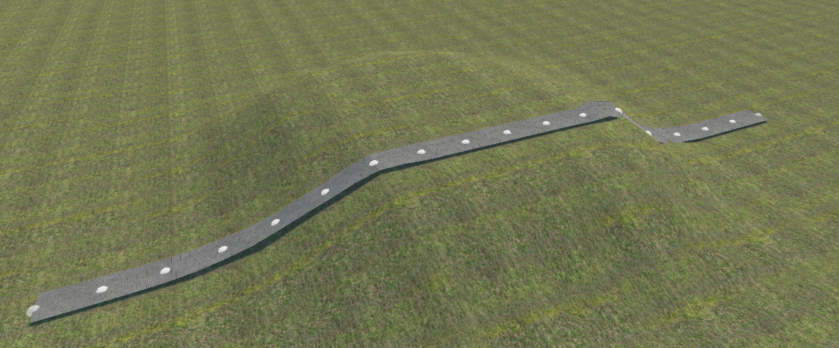
- Click FIT SPLINE TO TERRAIN.
- The spline subdivides into a dense chain following the hill profile:
G. Duplicating Parallel to Reference (FIT SPLINE TO SPLINE BELOW)
Clones an existing alignment to generate perfectly parallel corridors (e.g., sidewalks, curbs, guardrails alongside roadways):
Example 1: Lateral Offset (X Offset = -4.0 m)
- Place a straight sidewalk segment and select its nodes over the roadway:
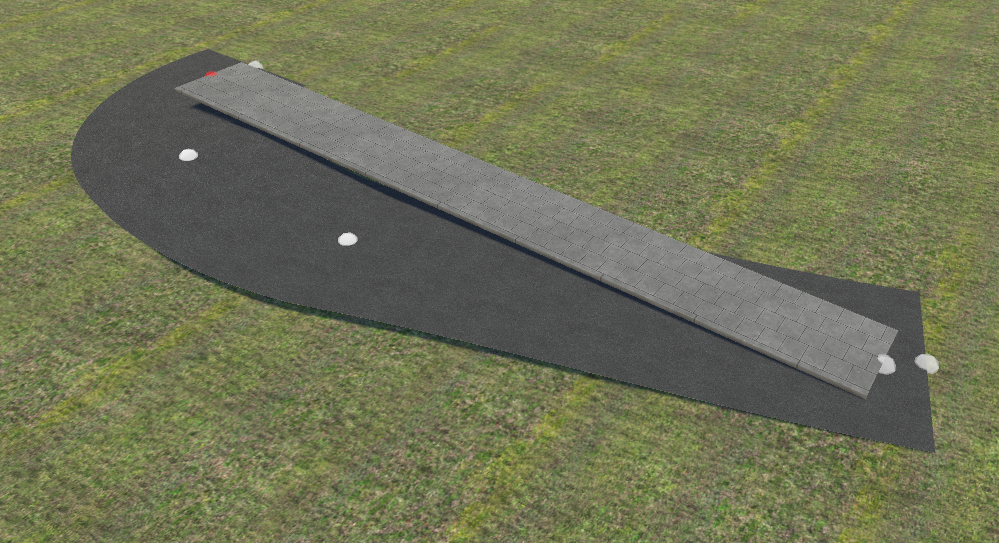
- Set X OFFSET to
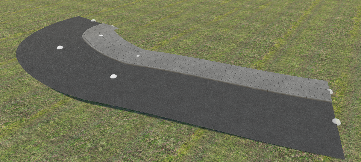
-4m and Z OFFSET to0m. - Click FIT SPLINE TO SPLINE BELOW.
- The sidewalk duplicates the entire roadway path and curve radius with an exact -4 m lateral offset:
Example 2: Vertical Lift (Z Offset = 0.1 m, X Offset = 0)
- Place a spline overlapping the roadway:
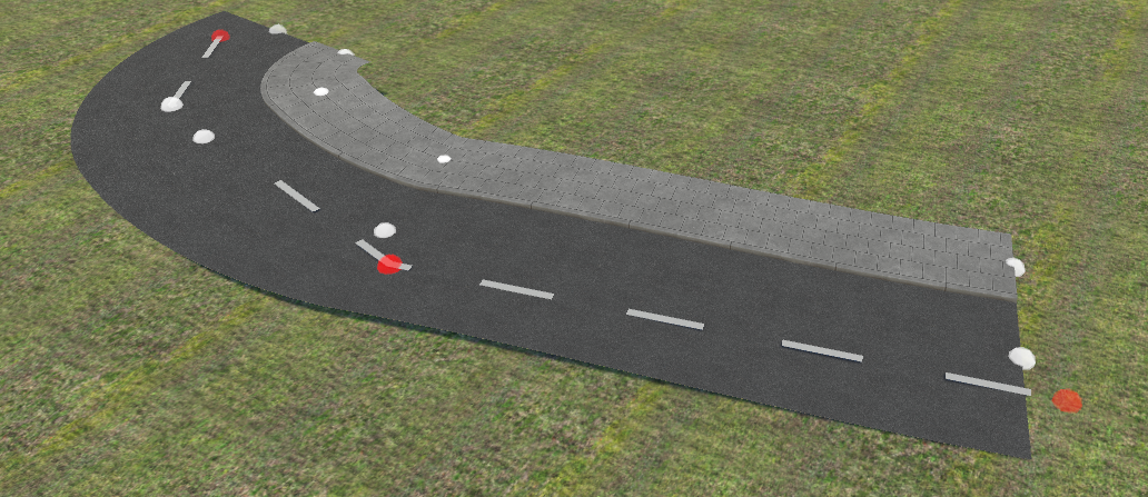
- Set X OFFSET to
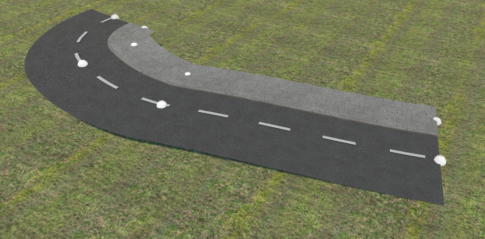
0m and Z OFFSET to0.1m (10 cm above asphalt). - Click FIT SPLINE TO SPLINE BELOW.
- The spline clones along the entire length elevated by 10 cm:
8. Fragments Mode (FRAGMENTS)
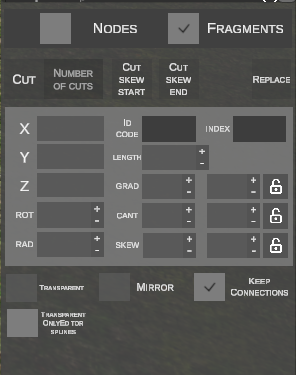
In FRAGMENTS mode, spline segments are selected as single bodies by clicking on their surface (highlighted in red):
A. Placing and Appending Fragments
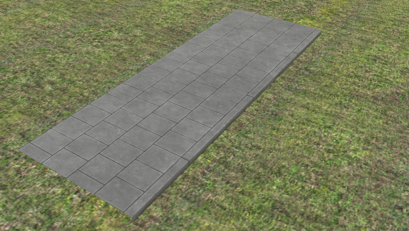
- Placing a New Fragment: Select a profile and press N. The fragment spawns under the cursor:
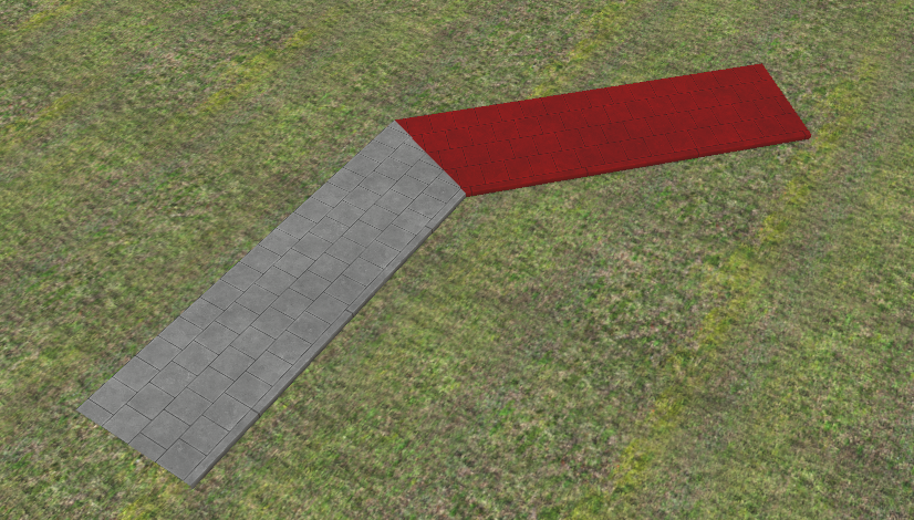
- Extending a Fragment: Select a fragment and press N. An adjacent fragment appends directly to its end:
B. Subdividing Splines (CUT)
Splits the selected spline segment into multiple equal parts along its length:
- Select the fragment with LMB.
- In the NUMBER OF CUTS field, set the cut count (keys + / - step values live):
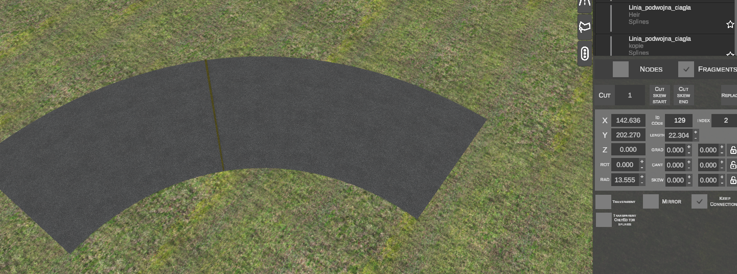
- Click CUT.
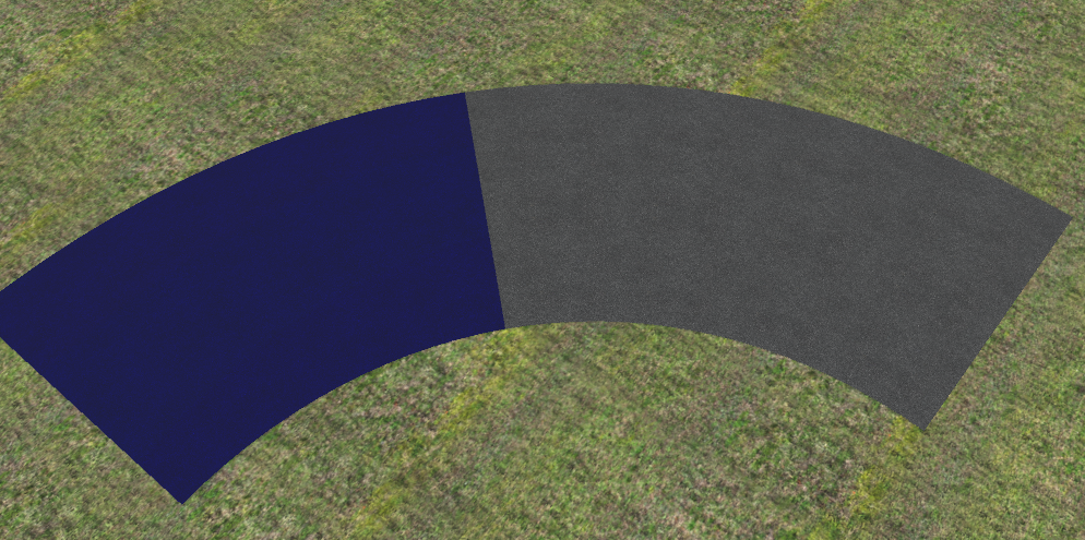
- The spline divides into independent sub-segments:
C. Additional Tools in Fragments Mode
- CUT SKEW START / END: Adjusts skew joint angles interactively using the mouse.
- REPLACE: Replaces the profile of the selected spline with the profile active in the library.
- MIRROR: Inverts the cross-sectional profile (swaps left and right curb profiles).
- KEEP CONNECTIONS: Preserves connectivity with neighboring segments during parameter edits.
- HALF TRANSPARENT SPLINE (key: H): Toggles semi-transparency in the viewport.
- TRANSPARENT ONLYEDITOR SPLINES: Forces transparency for editor-only guide splines.
9. Keyboard Shortcuts Summary
Nodes Mode (NODES)
| Shortcut | Function | Description |
|---|---|---|
| N | New Spline / Extrude | Without selection: spawns new spline. With node selected: extrudes new spline from that node. |
| G | Grab (Move) | Translates selected node horizontally. |
| Z | Height Z (Linear) | Modifies node elevation maintaining a straight linear slope. |
| X | S-curve Height | Smooth dual-transition curve with flat tangents at both ends. |
| C | Sag Curve (Ease-in) | Vertical curve with flat base tangent and steep exit at moving node. |
| V | Crest Curve (Ease-out) | Vertical curve with steep start and flat crest tangent at moving node. |
| R | Toggle Straight / Curve | Toggles segment geometry live between straight and arc. |
| Alt | Match Tangent Angle | Re-aligns spline heading tangentially to the predecessor. |
| Ctrl (hold) | Node Snapping | Snaps moving node to nearby existing nodes. |
| H | Semi-transparency | Toggles semi-transparency for selected splines. |
[ / ] |
Node Handle Scale | Decreases or increases the visual diameter of node spheres in the scene. |
| Del | Delete | Deletes the selected node or spline segment. |
| Esc | Cancel | Aborts active action or deselects items. |
Fragments Mode (FRAGMENTS)
| Shortcut | Function | Description |
|---|---|---|
| N | New Fragment | Places a new segment or appends one to the selected fragment's end. |
| G | Move Fragment | Translates the entire selected fragment horizontally. |
| Z | Fragment Height | Shifts vertical elevation of the entire segment. |
| R | Rotate Fragment | Rotates the fragment around its vertical axis. |
| Ctrl + R | Adjust Skew | Adjusts Skew joint angle using vertical mouse dragging. |
| Ctrl + C | Copy | Copies selected fragments to the clipboard. |
| Ctrl + V | Paste | Pastes copied fragments under the mouse cursor. |
| + / - | Cut Count | Increases or decreases cut subdivisions in the Cut tool. |
| Del | Delete Fragment | Deletes the selected spline fragment. |