Custom Shapes Tab
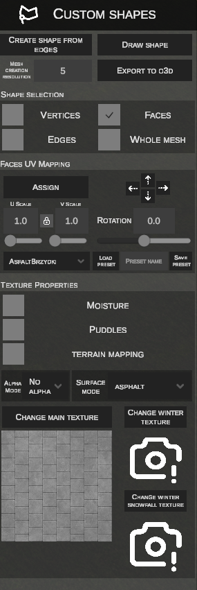
The Custom Shapes tab (accessible via the polygon mesh icon in the side toolbar) is used for generating, editing, and texturing arbitrary 3D mesh surfaces directly in the nEditor viewport, as well as compiling them into native OMSI scenery object formats (.o3d / .sco).
The tool allows you to model irregularly contoured surfaces – either by freehand polygon sketching or by automatically bridging spaces between edges of splines and other existing shapes.
1. Freehand Shape Drawing (DRAW SHAPE)
The DRAW SHAPE mode enables freeform drafting of surface contours over the terrain using control vertices.
Step-by-Step Drawing Workflow:
- Click DRAW SHAPE in the side panel.
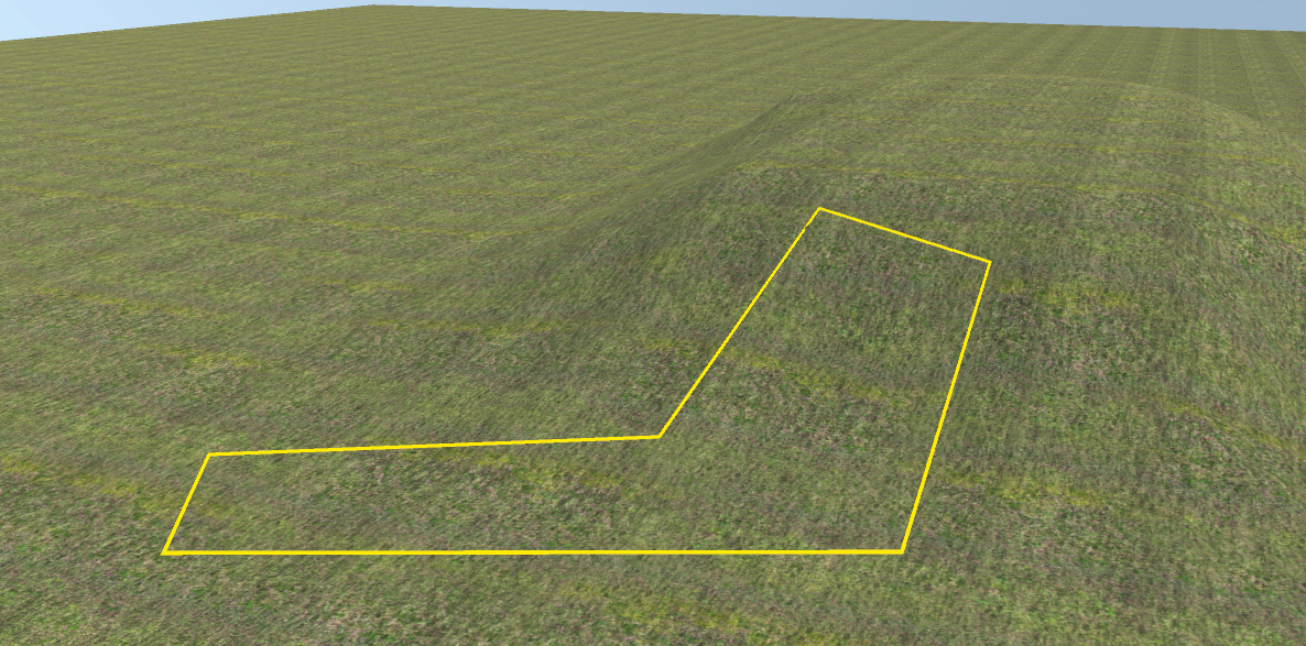
- Click LMB across the terrain surface to place consecutive contour vertices. A yellow preview outline is drawn between points.
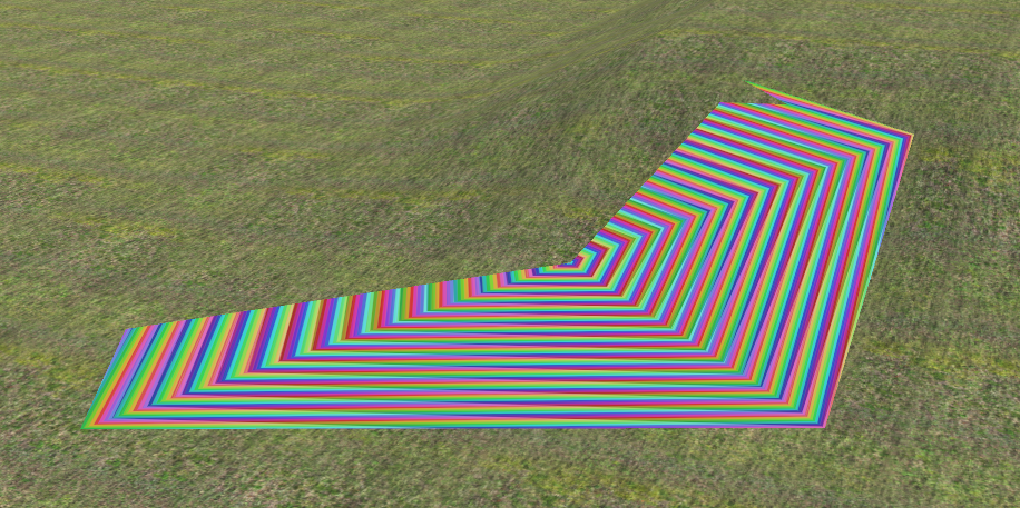
- To close the contour and generate the 3D mesh:
- Click LMB near the initial point (within 0.3 m), OR
- Press Enter or F (minimum 3 vertices required).
- The editor automatically triangulates the polygon, generates a 3D mesh, and switches into face selection mode (Faces).
- Pressing Esc before closing aborts the drawing.
2. Generating Mesh from Edges (CREATE SHAPE FROM EDGES)
The CREATE SHAPE FROM EDGES tool builds a smooth polygon mesh bridging the gap between existing elements – longitudinal or transversal spline edges as well as boundaries of existing custom meshes.
Step-by-Step Edge Generation:
- Click CREATE SHAPE FROM EDGES in the side panel.
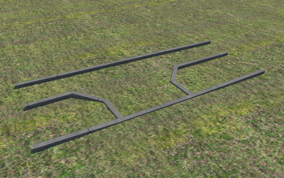
- Prepare the workspace area between splines or shapes to be joined:
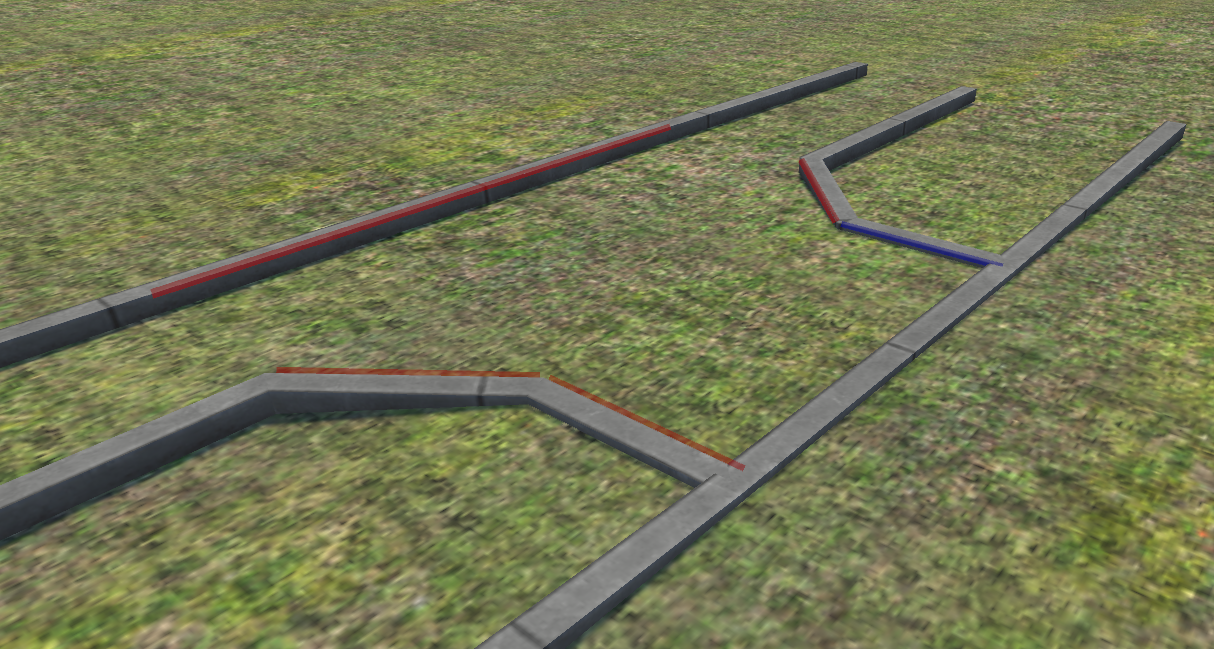
- Hover over a spline edge (highlights blue) and click LMB to select it (highlights red):
- In the MESH CREATION RESOLUTION field, set sampling density (e.g., 5 subdivisions along curves):
- Press the F key. The editor builds a triangle mesh bridging the selected edges:
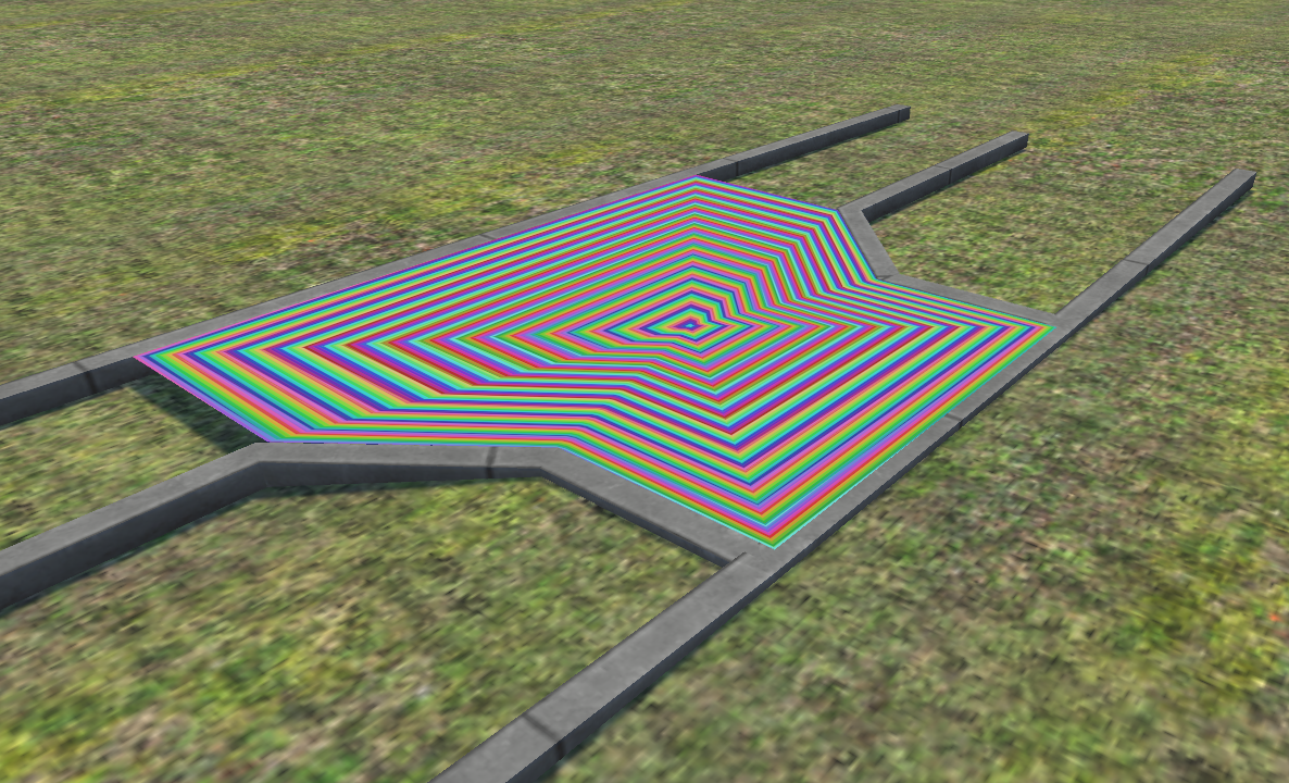
- You can select edges not only from splines but also from previously generated custom shapes:
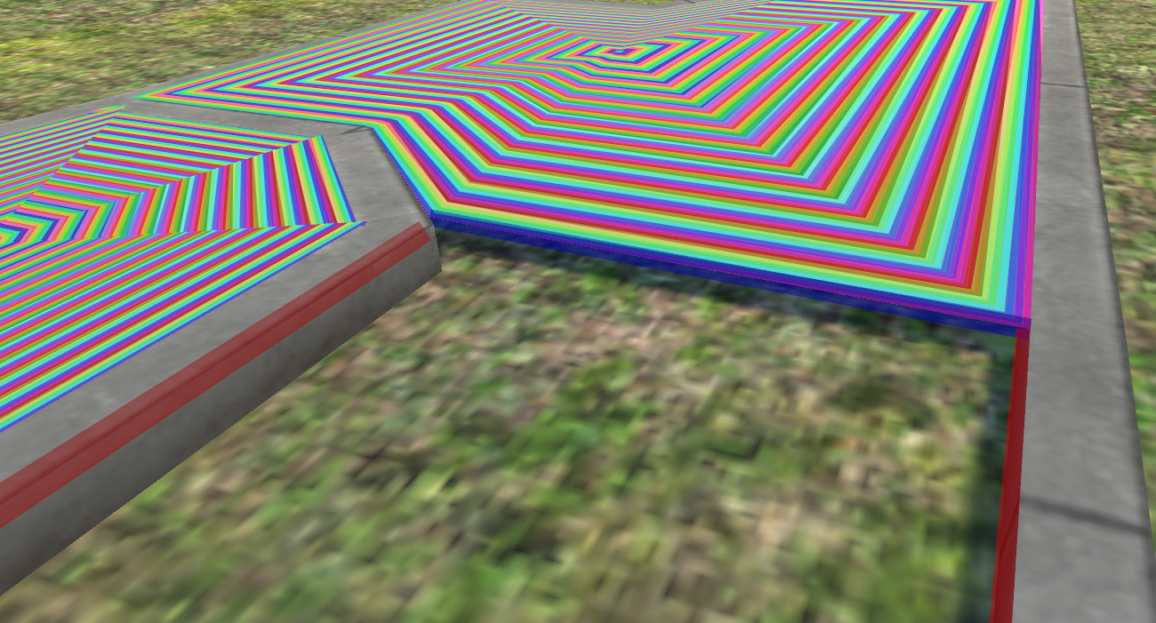
- Repeating the process fills all adjacent segments:
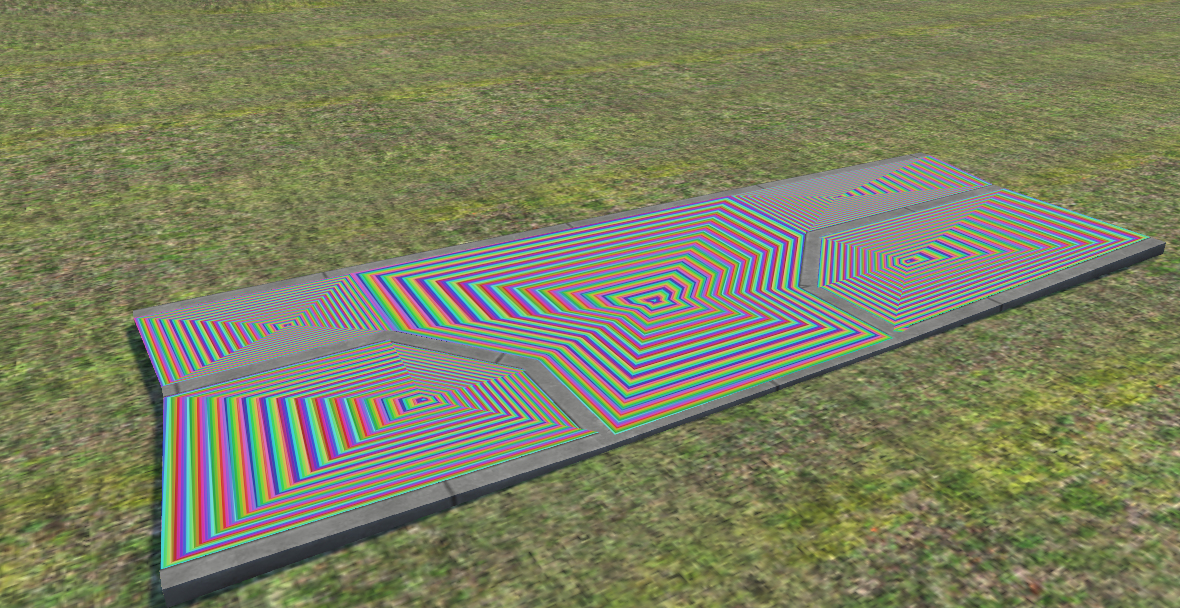
- Extrusion in Creation Mode: Instead of bridging between two edges, select a single edge and press E to extrude new geometry tracking the mouse cursor.
3. Geometry Selection Modes (SHAPE SELECTION) and 3D Manipulation
Once a mesh is generated, four sub-element selection levels become available:
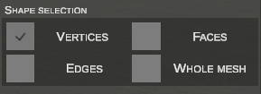
Universal Selection Rules:
- LMB Click: Selects the element under cursor (deselects others).
- Box Select (Drag LMB): Selects all elements within the bounding box.
- Shift + LMB / Box: Adds elements to the active selection.
- Ctrl + LMB / Box: Removes elements from the active selection.
A. Vertices Mode (VERTICES)
In VERTICES mode, all mesh nodes appear as points (white – inactive, yellow – hovered, red – selected).
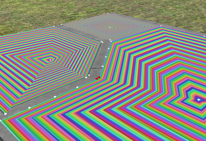
- G (Move Horizontal): Translates selected vertices freely in the horizontal X/Z plane.
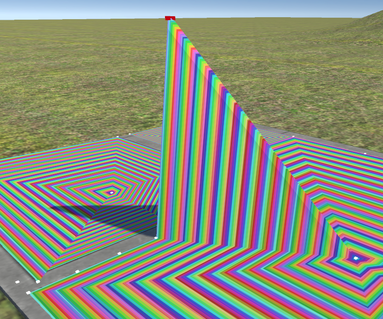
- Z (Vertical Height): Adjusts vertex elevation. Mouse movement raises or lowers points, creating terrain steps, curbs, ramps, or cross-slopes:
- R (Rotate): Rotates selected vertices around their common center.
- Del: Deletes selected vertices along with adjacent faces.
- Confirmation and Cancellation: Click LMB, press Enter or Space to confirm. Click RMB or press Esc to cancel.
B. Edges Mode (EDGES)
In EDGES mode, you can select individual mesh edges (highlighted in green).
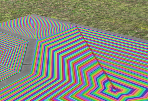
- E (Extrude Edges): Extrudes new polygon faces from selected edges. Moving the cursor stretches the new segment, and clicking LMB commits the placement:
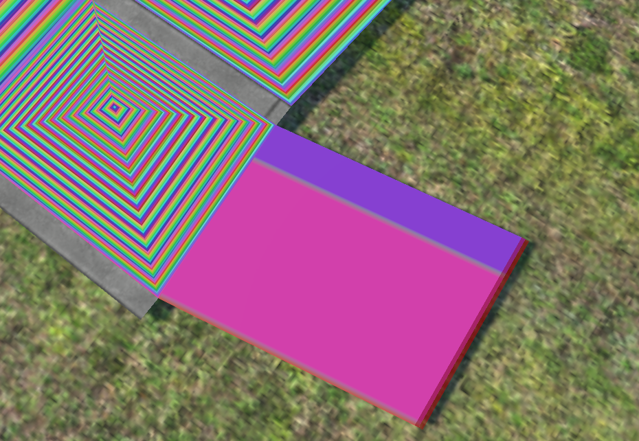
- G (Move Horizontal): Translates selected edges across the X/Z plane.
- Z (Height): Raises or lowers selected edges vertically.
- R (Rotate): Rotates selected edges.
- Del: Deletes selected edges.
C. Faces Mode (FACES)
FACES mode selects triangle polygons for texturing, transformation, or topological edits. Selected faces highlight in semi-transparent orange.
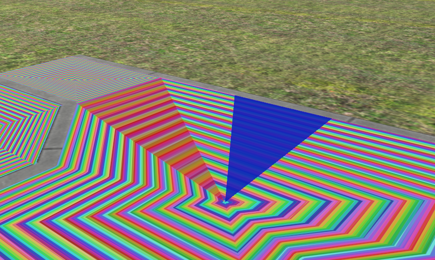
- Texturing and UV Mapping: Materials and mapping properties are assigned via
FACES UV MAPPING. - G / Z / R: Move, raise, and rotate selected faces.
- Left / Right / Up / Down: Precisely shifts texture coordinates (UV Offset) across selected faces.
- Del: Deletes selected faces.
D. Whole Mesh Mode (WHOLE MESH)
Treats the entire generated geometry as a single rigid body object.
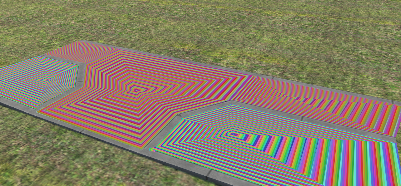
- G / Z / R: Move horizontally, adjust elevation, or rotate the entire mesh.
- S (Scale): Proportionally scales the entire 3D mesh volume based on cursor distance from the object center.
- Del: Deletes the whole mesh.
- Export: Selecting the mesh in this mode enables the EXPORT TO O3D button.
4. Texturing and UV Mapping (FACES UV MAPPING)
The FACES UV MAPPING panel applies materials to selected faces with precise control over scale, offset, and rotation.
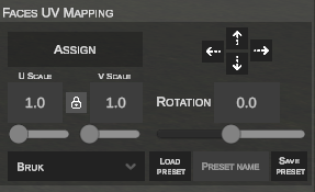
Texture Application Workflow:
- Switch to FACES or WHOLE MESH mode and select the target faces.
- Select a texture from the thumbnail bar (or import a new file from disk):

- Click ASSIGN. The texture is applied to selected surfaces immediately:
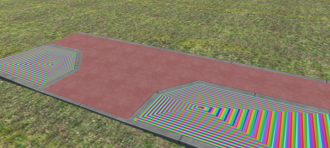
Supported File Extensions
Supported formats include .jpg, .png, .tga, and .dds. .bmp is not supported. Filenames must be unique to prevent overwriting assets with identical names.
Scaling Textures (U SCALE / V SCALE) and Aspect Lock
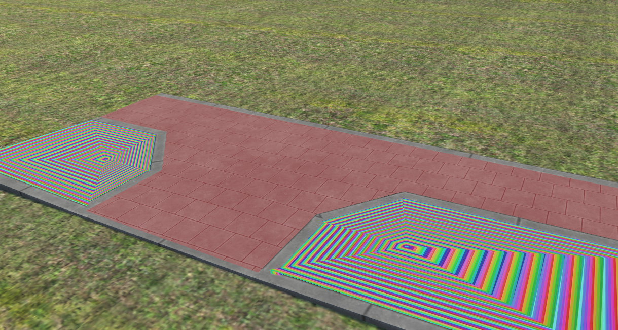
- Locked Aspect Ratio (Square): By default, the padlock icon is locked. Adjusting
U SCALEautomatically updatesV SCALEproportionally: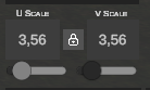
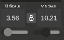
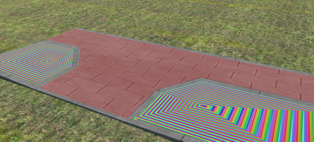
- Unlocked Aspect Ratio (Independent U and V axes): Clicking the padlock opens it, enabling non-uniform stretching across the horizontal (U) and vertical (V) axes:
Offset and Rotation
- UV Offset: Click the arrow buttons in the panel (
▲,▼,◄,►) or use keyboard arrow keys (Up, Down, Left, Right) to shift texture patterns across faces (aligning seams, paver lines, or curb edges). - ROTATION: Slider and numeric input rotate the texture from
0°to360°.
UV Presets (UV PRESETS)
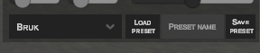
Frequently used mapping ratios can be saved as presets:
- Saving a Preset: Enter a unique name in PRESET NAME and click SAVE PRESET.
- Loading a Preset: Select a preset from the dropdown and click LOAD PRESET to apply scale and rotation to selected faces instantly.
5. Advanced Material Properties (TEXTURE PROPERTIES)
Defines physical surface response, weather behavior, and transparency rendering in OMSI 2:
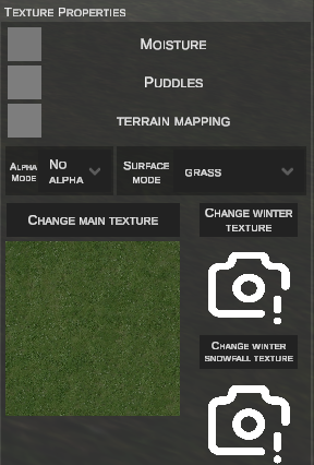
Surface and Projection Options:
- MOISTURE: Enables dynamic wetness shading during rainfall.
- PUDDLES: Generates water puddles on the surface in rainy conditions.
- TERRAIN MAPPING:
- When disabled, texturing aligns with the polygon's local UV space:

- When enabled, texture projection matches the global terrain grid, eliminating visible seams with adjacent ground:
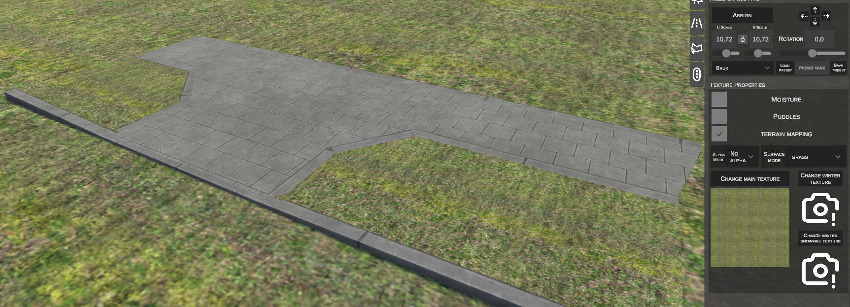
- When disabled, texturing aligns with the polygon's local UV space:
Alpha Transparency Modes (ALPHA MODE)
Controls how texture alpha transparency is interpreted:
| Mode | Function |
|---|---|
| No Alpha | Ignores alpha; 100% opaque. |
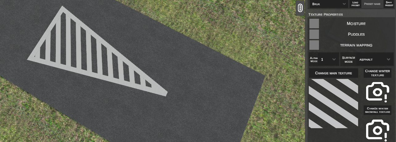
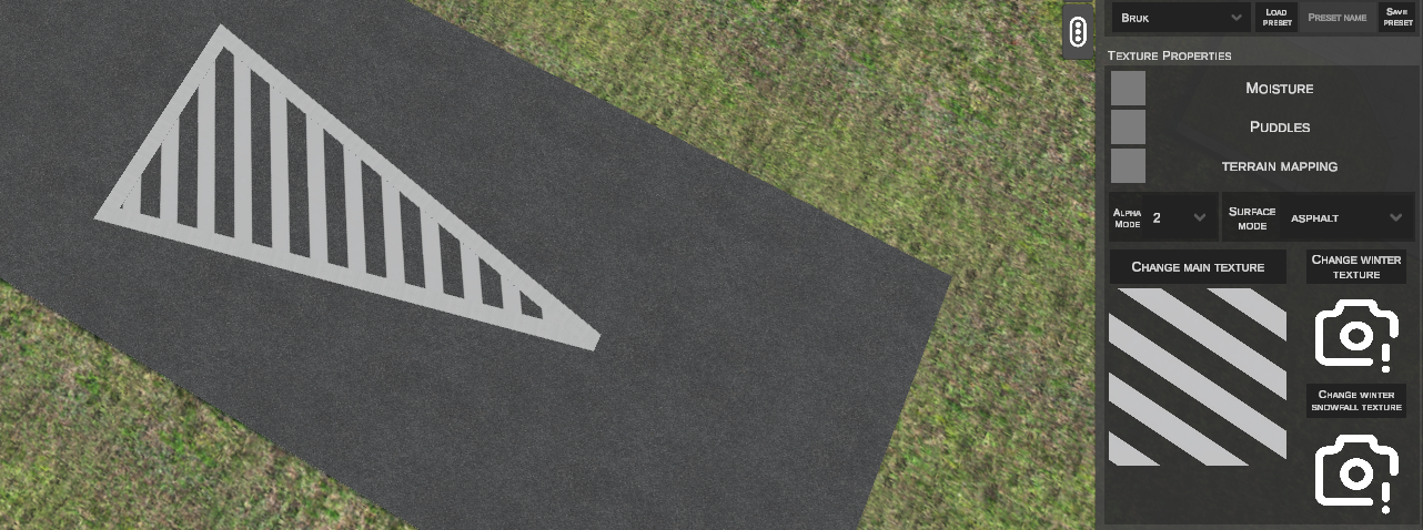
| Alpha 1 | 1-bit transparency testing (cutout mask 0 or 1). Pixels are fully opaque or fully transparent. |
| Alpha 2 | Smooth alpha blending (translucent gradients). |
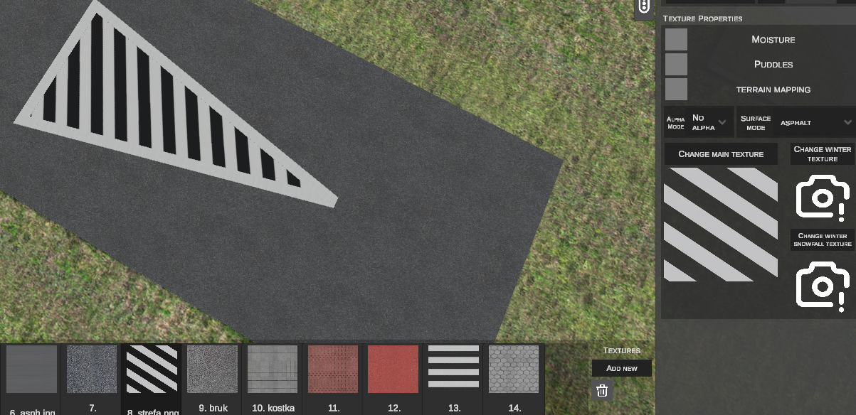
Physical Surface Type (SURFACE MODE)
Defines the physical ground type for vehicle wheel traction and tire/footstep sound effects in OMSI 2:
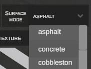
Available surface types:
* asphalt – asphalt
* concrete – concrete
* cobblestone – cobblestone
* dirt – dirt track / earth
* grass – grass
* gravel – gravel / ballast
* snow – packed snow
* deep snow – deep snow
* slush – slush
* ice – ice / black ice
* water – water
* mud – mud
* sand – sand
* metal – steel deck / bridge
* wood – timber planks
* small cobblestone – small granite setts
* interlocking paver – interlocking concrete pavers (Polbruk/Bauma)
Seasonal Texture Variants (Winter Textures)
Assigns alternative texture graphics for specific seasons and weather:
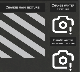
- CHANGE MAIN TEXTURE: Selects the standard spring/summer texture.
- CHANGE WINTER TEXTURE: Assigns dry winter texture (without active snowfall).
- CHANGE WINTER SNOWFALL TEXTURE: Assigns the texture rendered during active snowfall.
6. Exporting to Native OMSI Format (EXPORT TO O3D)
Custom shapes can be compiled into .o3d geometry and .sco scenery object definition files at any time:
Export Is Not Mandatory
Manual export of custom shapes is not required prior to exporting the map to OMSI 2. During standard map export, nEditor automatically converts custom shapes into scenery objects (1 per tile) while preserving metadata for subsequent editing in the "Custom Shapes" tab. After manual export via this button, further topological edits in this tab will no longer be possible.
Step-by-Step Export Workflow:
- In SHAPE SELECTION, switch to WHOLE MESH mode.
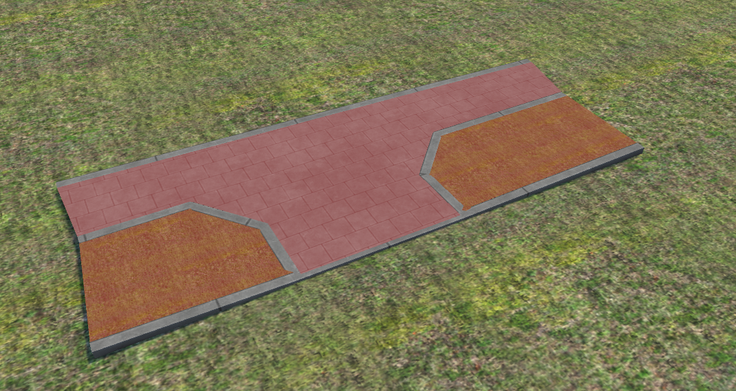
- Click LMB on the target mesh (highlights orange):
- The EXPORT TO O3D button in the top bar highlights and becomes active:
- Click EXPORT TO O3D.
- The editor automatically:
- Compiles geometry into a binary
model.o3dfile. - Generates an
.scodefinition file inSceneryobjects/nEditorGenerated/...with material and alpha tags. - Copies referenced textures to the object's folder.
- Replaces the temporary workspace mesh with the permanent OMSI scenery object instance bound to the tile.
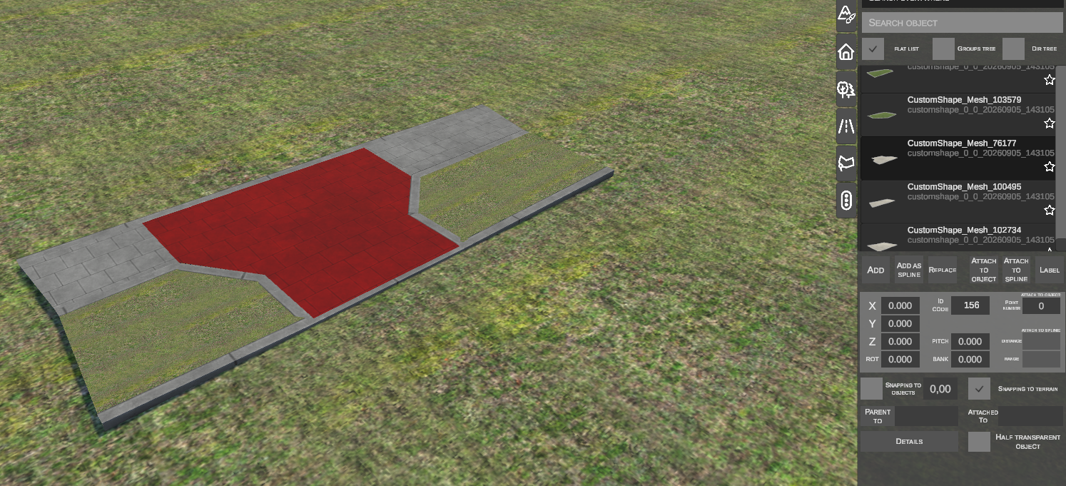
- Navigating to the Scenery Objects tab and clicking REBUILD LIBRARY makes the new object available for placement across the map.
7. Keyboard Shortcuts Reference
| Shortcut | Context / Mode | Function |
|---|---|---|
| F | CREATE SHAPE FROM EDGES | Generates triangle mesh bridging selected edges. |
| E | CREATE SHAPE FROM EDGES | Initiates face extrusion from the selected edge. |
| LMB (near start) / Enter / F | DRAW SHAPE | Closes boundary contour and generates 3D mesh. |
| G | Vertices / Edges / Faces / Whole Mesh | Initiates horizontal translation (Grab). |
| Z | Vertices / Edges / Faces / Whole Mesh | Adjusts vertical elevation. |
| R | Vertices / Edges / Faces / Whole Mesh | Rotates selected sub-elements. |
| S | Whole Mesh | Scales the entire mesh volume proportionally. |
| E | Edges | Extrudes selected edges. |
| Left / Right / Up / Down | Faces / Whole Mesh | Shifts texture coordinates (UV Offset) across faces. |
| Shift + LMB / Box | Selection | Adds elements to current selection. |
| Ctrl + LPM / Box | Selection | Removes elements from current selection. |
| Del | All modes | Deletes selected vertices, edges, faces, or the whole mesh. |
| LMB / Enter / Space | During transform (Grab/Scale/Extrude) | Confirms geometry modification. |
| RMB / Esc | During transform (Grab/Scale/Extrude) | Aborts operation and restores geometry. |
| Esc | Draw Shape / Create from Edges | Aborts active tool and returns to Faces edit mode. |